


Touch Panel Accessories
42
VG-Series Modero Touch Panels
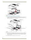
8. Grasp both the LCD and housing and then rotate the entire unit back onto a flat surface.
9. Insert all connectors and apply power.
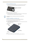
Installation and Upgrade of the Internal NXD Components
Upgrading the components within a WallMount panel involves removing the rear plastic outer housing
(back box), removing and/or installing an existing component, and then placing the back box back onto
the NXD panel, as described in the following sections.
Step 1: Remove the existing NXD Outer Housing
1.
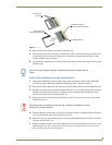
Carefully detach all connectors from the side of the touch panel and remove the front magnetic
faceplate from the NXD unit by firmly gripping the faceplate and pulling outwards, while applying
a small amount of pressure to remove it from the main unit.
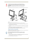
2. Place the LCD facedown onto a soft cloth to expose the under-side of the unit. This step helps
prevent scratching of the LCD.
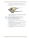
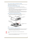
3. Unscrew the Stereo Output nut from the Stereo Output jack.
4. Remove the I/O connector plate by using a grounded Phillips-head screwdriver to remove the two
screws and slide the I/O connector plate away from the back box housing.
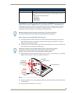
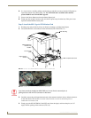
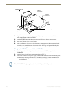
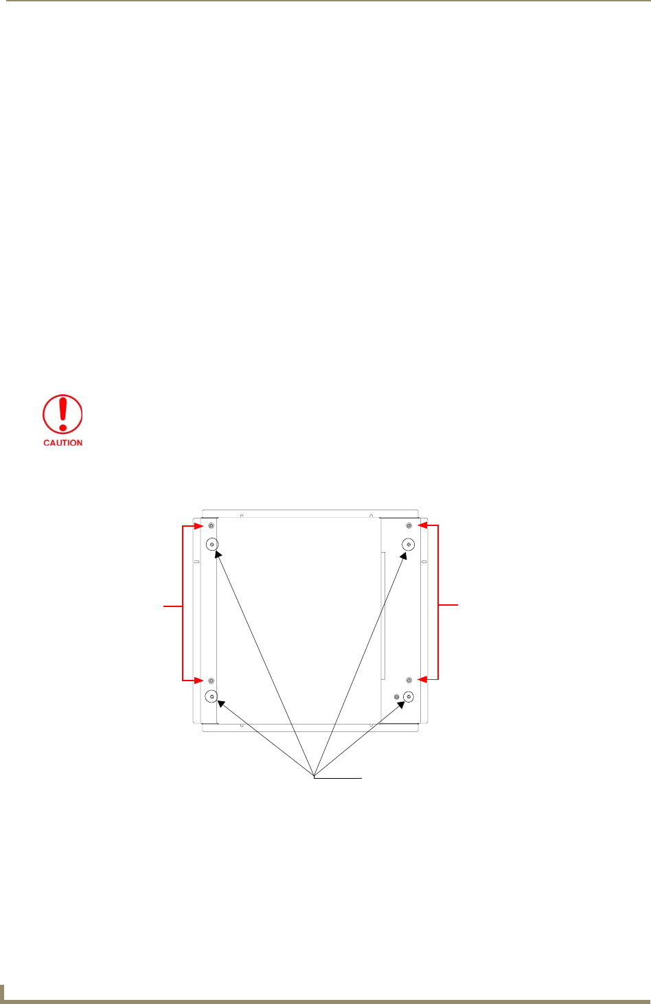
5. Unscrew the four pan-head Housing Screws from the rear of the NXD unit (FIG. 22) and gently
remove the outer housing. These four screws secure the back box to the internal panel casing.
DO NOT REMOVE THE PANEL SECURING SCREWS. These screws secure the
LCD to the metallic casing.
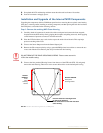
FIG. 22 Location of the securing screws on an NXD panel
Unscrew these four Housing Screws
DO NOT
these
DO NOT REMOVE
REMOVE
panel
securing
screws
these panel
securing screws
to remove the back box.
These make direct contact with the black
outer housing.