


Installation Procedures: 12" and 15" Panels
65
VG-Series Modero Touch Panels
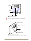
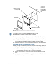
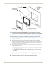
5. Connect all data and power wiring to their corresponding locations along the side of the
(un-powered) NXD touch panel.
Verify the terminal end of the power cable is not connected to power supply before plugging in
the 2-pin power connector.
The USB connectors can be from a either a USB extension cable, or a wireless USB RF
transmitter.
6. Test the incoming wiring by connecting the panel connections to their terminal locations and
applying power. Verify the panel is receiving power and functioning properly before finalizing the
installation.
7. Disconnect the terminal end of the power cable from the power supply.
8. Carefully slide the main unit into the cutout until the Mounting Tabs of the NXD unit lie flush
against the wall.
9. Insert and secure the four #4 screws into their corresponding holes located along the sides of the
NXD (using a grounded Phillips-head screwdriver) until the unit is secure and flush against the wall.
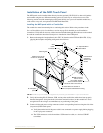
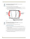
10. Reinstall the magnetic faceplate (A in FIG. 45) back onto the main NXD unit (B in FIG. 45).
Make sure to align the Microphone, Light, and PIR Motion sensor locations to their respective
openings on the front bezel/faceplate.
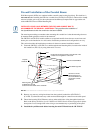
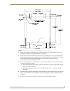
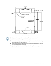
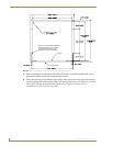
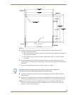
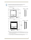
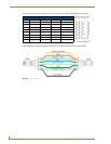
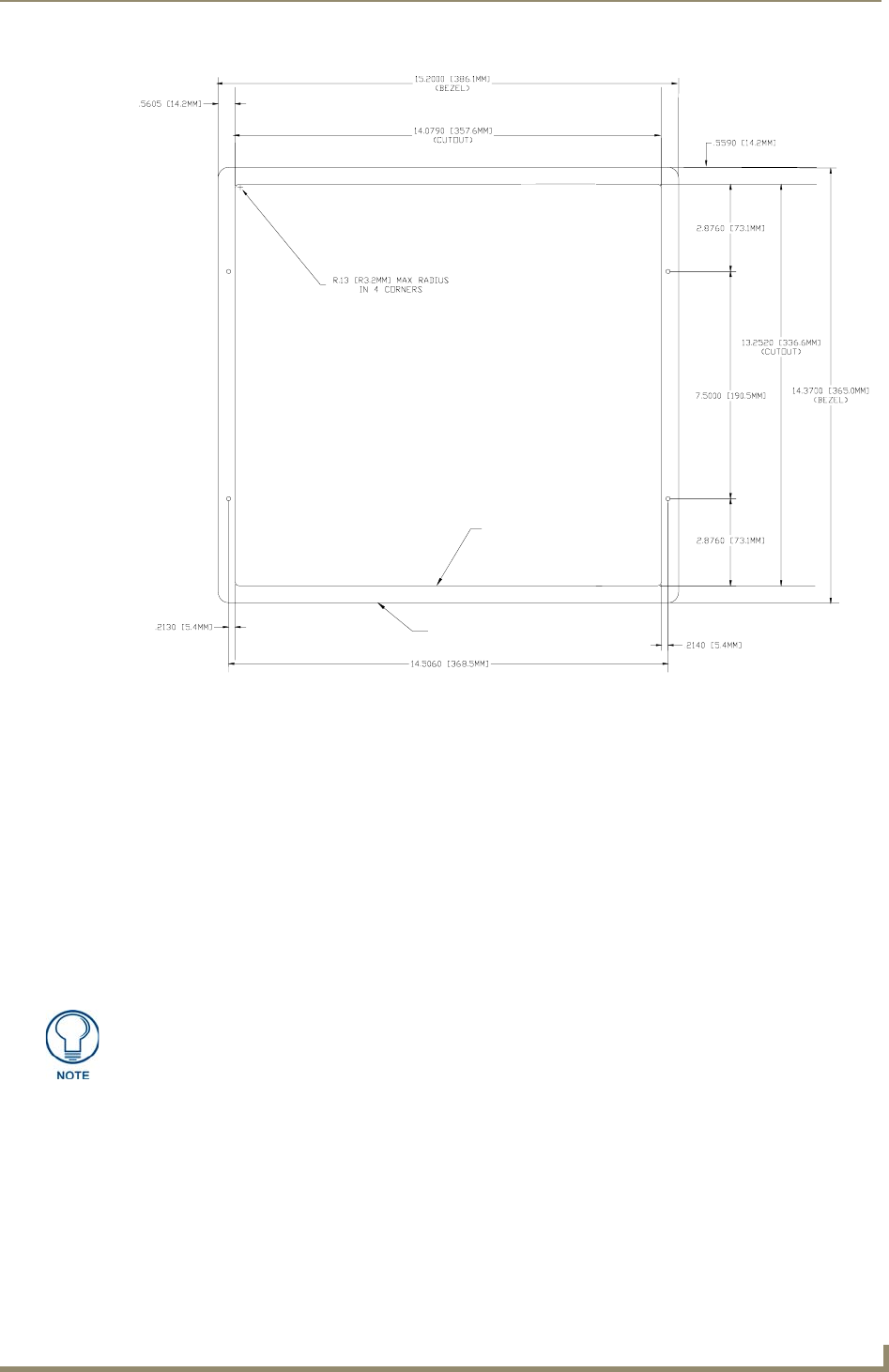
FIG. 44 NXD 15-inch Wall Mount panel dimensions using #4 mounting screws
FRONT BEZEL
CUTOUT
Don’t disconnect the connectors from the touch panel. The unit must be installed with
the necessary connectors before being inserted into the solid surface.