


Installation Procedures: 17" Panels
82
VG-Series Modero Touch Panels
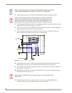
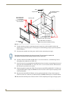
11. Connect all data and power wiring connectors to their corresponding locations along the side of the
(un-powered) NXD touch panel.
Verify the terminal end of the power cable is not connected to a power supply before plugging
in the 2-pin power connector.
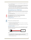
The USB connectors can be from either a USB extension cable, or a wireless USB RF
transmitter.
12. Test the incoming wiring by attaching the panel connections to their terminal locations and applying
power. Verify the panel is receiving power and functioning properly to prevent repetition of the
installation.
13. Disconnect the terminal end of the power cable from the connected power supply.
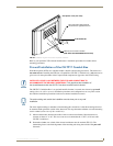
14. Follow the procedures outlined within Steps 1 - 5 on page 42 thru page 43 to carefully reinstall the
LCD panel back into the back box housing.
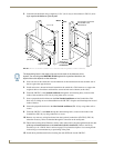
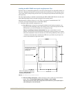
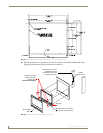
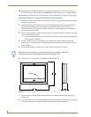
15. Install the four sets of drywall screws and expansion clips into the four oval notch locations along
the top/bottom edges of the main unit (FIG. 60). Make sure the top drywall clip grooves face
upwards and the bottom clip grooves face downwards (so they extend away from the Main unit).
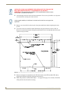
16. Carefully insert the main unit (with expansion clips) into the cutout until the Mounting Tabs
on the NXD unit lie flush against the wall (FIG. 60). Make sure to have the right side of the box
resting against the non-notched beam (on the right) and the connector-side of the unit pressed into
the notched beam (on the left).
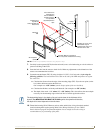
17. Tighten the drywall clip sets (screws and clips) until the Mounting Tabs are securely fastened and
flush against the wall.
18. Place the magnetic faceplate (A in FIG. 60) back onto the main NXD unit. Make sure to align the
Microphone, Light, and PIR Motion sensor locations to their respective openings on the front
bezel/faceplate.
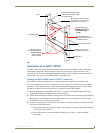
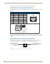
19. Reconnect the terminal RJ-45, Ethernet, and any optional audio/video wiring to their respective
terminal locations on either the NXA-AVB/RGB Breakout Box, Ethernet port, or NetLinx Master.
20. Reconnect the terminal power connector on the 12 VDC-compliant power supply and apply power.
Don’t disconnect the connectors from the touch panel. The unit must be installed with
the attached connectors before being inserted into the drywall.
Replacement drywall clip sets must be ordered from AMX.