


Touch Panel Accessories
22
VG-Series Modero Touch Panels
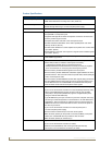
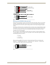
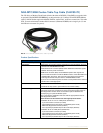
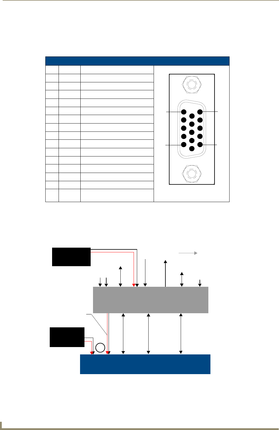
Using the HD-15 high-density connector
Connect the RGB/Comp source equipment HD-15 (male) connector to the RGB/COMPONENT HD-15
high-density connector (female) on the rear of the NXA-AVB/RGB Breakout Box. The following table
below lists the HD-15 connector pinouts.
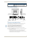
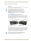
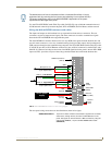
Installing the NXA-AVB/RGB
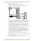
A 12 VDC-compliant power supply can indirectly provide power to a Modero panel by routing power
through the NXA-AVB/RGB Breakout Box. FIG. 3 shows a sample wiring configuration using both an
indirect or direct power connection for a VG-Series Modero panel.
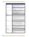
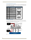
HD-15 Connector Pinouts
Pin Signal Function
1 Red Red signals/Cr
2 Green Green signals/Y
3 Blue Blue signals/Cb
4 N/A Not used
5 GND Signal Ground
6 RAGND Red analog ground
7 GAGND Green analog ground
8 BAGND Blue analog ground
9 N/A Not used
10 SAGND Synchronization analog ground
11 N/A Not used
12 N/A Not used
13 HSYNC Horizontal synchronization signal
14 VSYNC Vertical synchronization signal
15 N/A Not used
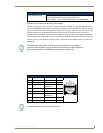
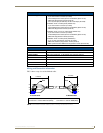
FIG. 3
Sample Wiring configuration using the NXA-AVB/RGB Breakout Box
HD-15 (male)
connector
10
6
5
1
15
11
VG-Series and Video-capable
Ethernet
12 VDC power
(RJ-45)
Video In
(BNC)
Mic Out
(4-pin)
Audio In
(6-pin)
NXA-AVB/RGB
Power
supplied via
Breakout Box
Audio/Video
(CAT5)
Line Level out
(to amplifier
or VOL card)
Touch Panels
or
Direct
Connect
Breakout Box
Ethernet
(rear)
(front)
(CAT5)
supply
Indirect
Connect
12 VDC power
supply
USB
(pass-thru)
RGB In (HD-15)
RGB (RGB and touch
control) (CAT5)