


Configuring Communication
96
VG-Series Modero Touch Panels
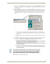
For Windows XP machines the setup program asks if you would like to create a restore point.
It is always a good idea to create restore points prior to installing new software.
Click the Next button when done.
9. At the end of the installation, press the Finish button.
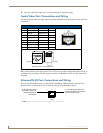
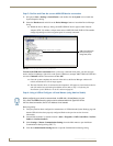
Step 2: Confirming the Installation of the USB Driver on the PC
The first time each AMX touch panel is connected to the PC it is detected as a new hardware device and
the USBLAN driver becomes associated with it (panel specific). Each time thereafter the panel is
"recognized" as a unique USBLAN device and the association to the driver is done in the background.
When the panel is detected for the first time some user intervention is required during the association
between panel and driver.
1. After the installation of the USB driver has been completed, confirm the proper installation of the
large Type-A USB connector to the PC's USB port, and restart your machine.
2. Connect the terminal end of the 12 VDC-compliant power supply cable to the power connector on
the rear/side of the touch panel and then apply power.
3. After the panel powers-up, press and hold the grey Front Setup Access button (for 3 seconds) to
continue with the setup process and proceed to the Setup page.
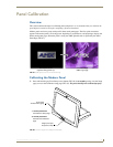
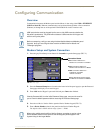
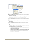
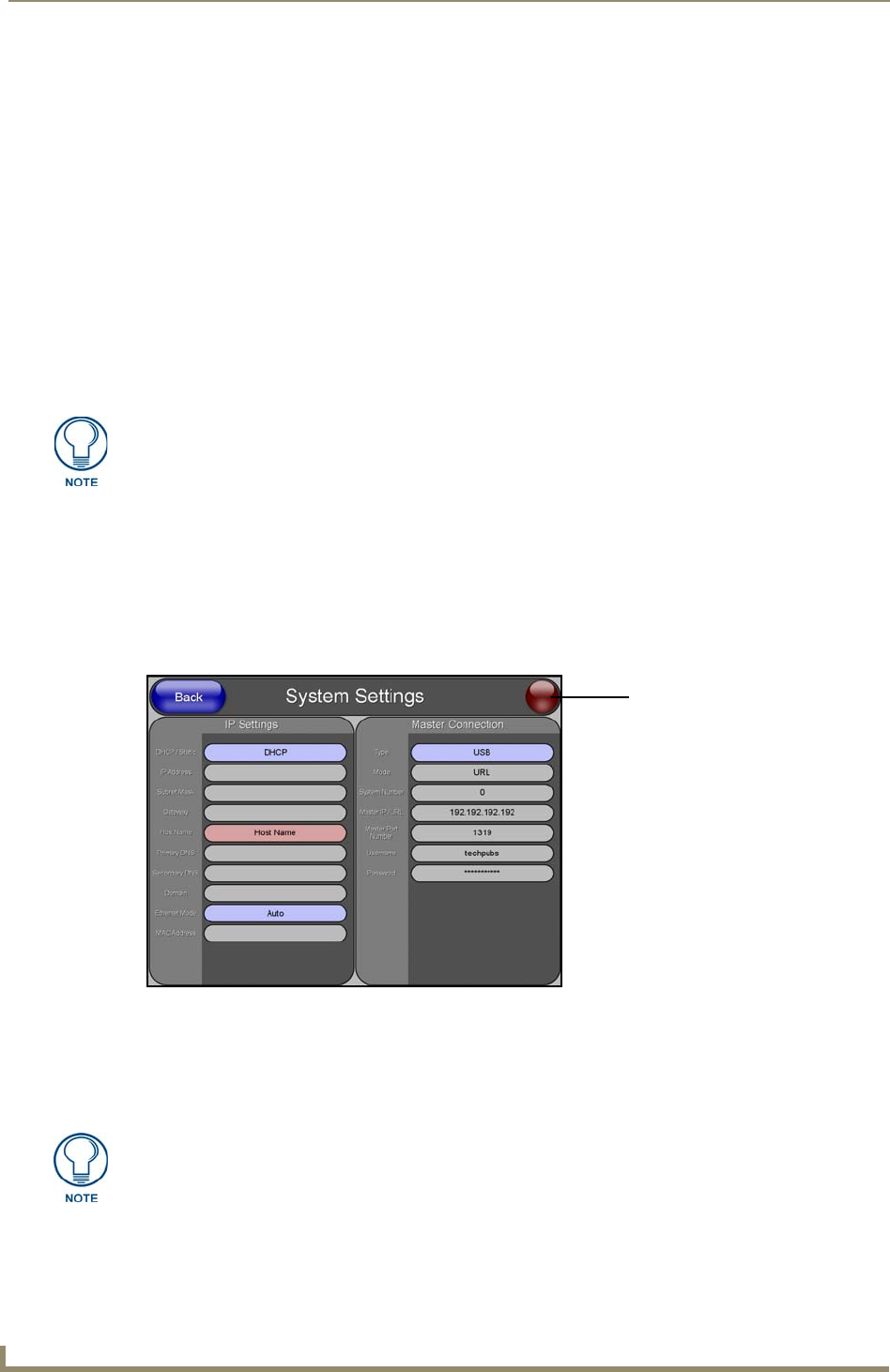
4. Select Protected Setup > System Settings (located on the lower-left) to open the System Settings
page (FIG. 74).
5. Toggle the blue Type field (from the Master Connection section) until the choice cycles to USB.
Refer to the System Settings Page section on page 166 for more information about the fields on this
page.
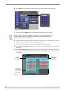
6. Press the Back button on the touch panel to return to the Protected Setup page.
If the panel is already powered, continue with steps 3.
The panel MUST be powered and configured for USB communication before
connecting the mini-USB connector to the panel’s Program Port.
FIG. 74 System Settings page - using a USB Connection Type
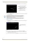
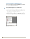
No connection is established until
the Virtual Master becomes
active within Studio
Red Connection Status icon -
Green Connection Status icon -
indicates no connection to a Master
indicates communication to a Master
Yellow Connection Status icon -
indicates an unreliable network
connection
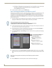
ALL fields are then greyed-out and read-only, but still display any previous network
information.