


Installation Procedures: 17" Panels
87
VG-Series Modero Touch Panels
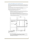
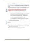
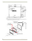
9. Use a grounded Phillips-head screwdriver to secure the NXA-RK17 to the equipment rack using
#10-32 screws (not included).
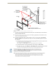
10. Place the magnetic faceplate back onto the main NXD unit by gripping the faceplate and placing it
on the housing with gentle force. Make sure to align the Microphone, Light, and PIR Motion sensor
locations to their respective openings on the front bezel/faceplate.
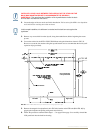
11. Reconnect the terminal RJ-45, Ethernet, and any optional audio/video wiring to their respective
terminal locations on either the NXA-AVB/RGB Breakout Box, Ethernet port, or NetLinx Master.
12. Reconnect the terminal power connector on the 12 VDC-compliant power supply and apply power.
Wiring Guidelines for the 1700VG Panels
1700VG panels use a 12 VDC-compliant power supply to provide power to the panel via the 2-pin 3.5
mm mini-Phoenix PWR connector. Use the previously referenced power requirements to determine the
power draw.
The incoming PWR and GND wires from the power supply must be connected to the corresponding
locations within the PWR connector.
Preparing captive wires
You will need a wire stripper and flat-blade screwdriver to prepare and connect the captive wires.
1. Strip 0.25 inch (6.35 mm) of insulation off all wires.
2. Insert each wire into the appropriate opening on the connector (according to the wiring diagrams
and connector types described in this section).
3. Tighten the screws to secure the wire in the connector. Do not tighten the screws excessively; doing
so may strip the threads and damage the connector.
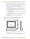
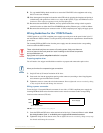
Wiring a power connection
To use the 2-pin 3.5 mm mini-Phoenix connector for use with a 12 VDC-compliant power supply, the
incoming PWR and GND wires from the external source must be connected to their corresponding
locations on the connector (FIG. 64).
1. Insert the PWR and GND wires on the terminal end of the 2-pin 3.5 mm mini-Phoenix cable. Match
the wiring locations of the +/- on both the power supply and the terminal connector.
2. Tighten the clamp to secure the two wires. Do not tighten the screws excessively; doing so may strip
the threads and damage the connector.
These units should only have one source of incoming power. Using more than one
source of power to the touch panel can result in damage to the internal components
and a possible burn out.
Apply power to the panels only after installation is complete.
Never pre-tin wires for compression-type connections.
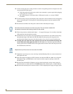
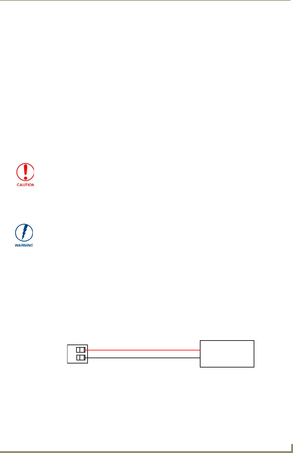
FIG. 64 NetLinx power connector wiring diagram
PWR +
GND -
To the Touch Panel
Power Supply