


Touch Panel Accessories
27
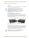
VG-Series Modero Touch Panels
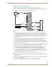
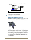
Wiring for Pass-Thru Computer Control
1.
Discharge any acquired static electricity by touching a grounded metal object.
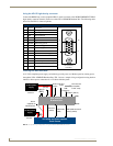
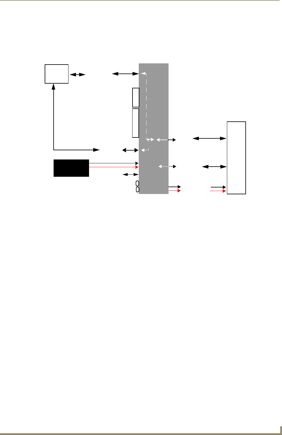
2. Turn-off your computer and remove any installed power cables. Review FIG. 7 for an overview of
the overall wiring configuration surrounding pass-thru control.
3. Use an HD-15 video cable to create a connection between the computer’s video output connector
and the HD-15 D-Sub RGB/VGA/Component connector on the rear of the NXA-AVB/RGB.
This HD-15 D-Sub RGB/VGA/Component connector on the breakout box is used to route an RGB
(computer) or Component (DVD/HDTV) signal to a target Modero panel (using the internal
NXA-RGB card).
4. Use a Type-A to Type-B USB cable to create a connection from USB connector on the computer to
the rear Type-B USB device port input connector on the rear of the NXA-AVB/RGB.
This connection routes pass-thru computer control from the touch panel, to the front RGB RJ-45
connector, and then through the rear USB port to the PC. Touch information is sent to and from the
panel via this two-way connector.
5. Verify the panel has been configured to communicate by connecting an RJ-45 10/100baseT Ethernet
connector from the rear Ethernet port on the breakout box to a valid Ethernet Hub.
6. Connect the incoming power connector to the 12 VDC power connector on the rear of the box.
DO NOT CONNECT POWER UNTIL THE UNIT IS COMPLETELY INSTALLED.
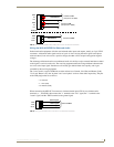
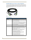
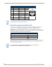
7. Use the NXA-MTC/RGB to create a connection between the NXA-AVB/RGB and the target
VG-Series touch panel. Refer to the following NXA-MTC/RGB Combo Table Top Cable (CA2250-
70) section on page 28 for more detailed cable information.
8. Connect a USB mouse/keyboard to the available connectors on the target touch panel.
9. Verify a proper installation of all of the RJ-45 and power connectors between the target touch panel
and breakout box.
10. Verify a proper installation of all of the RJ-45, HD-15, and power connectors between the rear of the
breakout box and the computer.
11. Provide power to both the computer and the NXA-AVB/RGB Breakout Box.
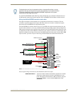
FIG. 7 Pass-thru control wiring configuration
NXA-AVB/RGB
Breakout
Box
F
R
O
N
T
R
E
A
R
Ethernet
Out (CAT5)
Power to
Ethernet
(RJ-45)
12 VDC power
supply
USB
(Type-B)
RGB
(CAT5)
RGB/Component In
(HD-15)
touch panel
PC
P
A
N
E
L
USB
(Type-A)