Installation Procedures: 17" Panels
85
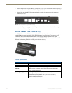
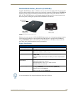
VG-Series Modero Touch Panels
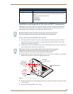
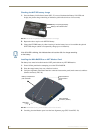
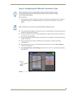
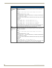
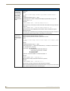
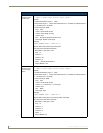
7. Carefully lay the separated LCD (from the main unit) onto a soft cloth resting on a level surface.
This soft cloth prevents scratching during the rest of the installation procedure.
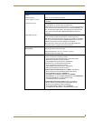
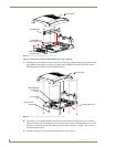
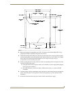
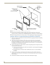
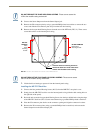
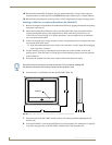
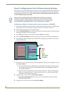
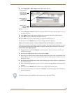
8. Insert the back box into the surface cutout to check for fit. Make any adjustments to the dimension
of the cutout to accommodate the back box.
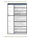
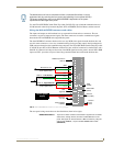
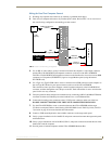
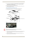
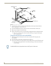
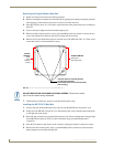
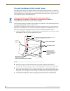
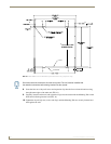
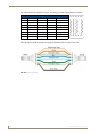
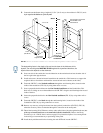
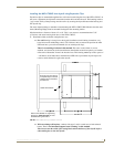
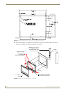
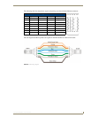
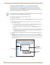
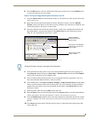
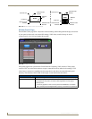
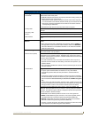
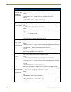
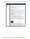
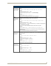
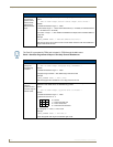
9. Cutout the notched beam (FIG. 62 on page 84) using a height of 13.554" (34.43 cm) and a depth
using the following guideline. This notched beam is located on the side of the NXD unit furthest
away from the connectors.
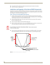
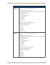
Calculate the distance from the edge of the mounting ridge (FIG. 62) to the rear point (on the
box) where the beam touches the back box.
Our example uses 1 3/8" (inches) (on the deepest point of the rear back box).
Calculate the thickness of the surface. Our example uses 5/8" (inches).
The depth of the notch: 1 3/8" minus 5/8" = 6/8" (inches). This value reflects the cutout depth
necessary for the mounting ridge on the back box to be flush against the surface.
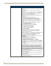
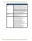
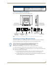
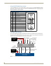
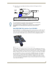
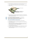
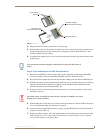
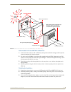
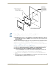
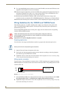
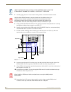
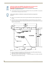
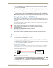
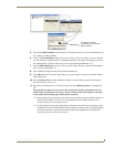
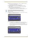
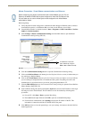
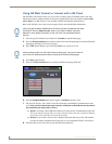
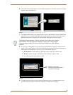
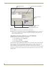
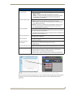
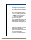
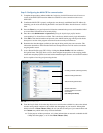
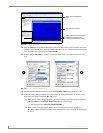
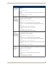
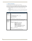
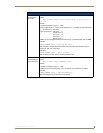
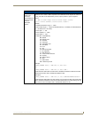
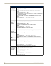
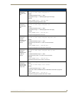
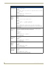
10. Thread the incoming RJ-45, Ethernet, and any other audio/video wiring (from their terminal
locations) through the cutout opening. Refer to the Wiring Guidelines for the 1700VG
Panels section on page 87 for pinout descriptions. Leave enough slack in the wiring to
accommodate any re-positioning of the panel.
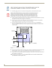
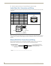
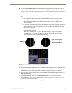
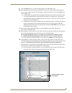
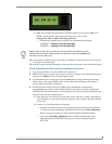
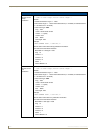
11. Connect all data and power wiring connectors to their corresponding locations along the side of the
(un-powered) NXD touch panel.
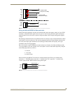
Verify the terminal end of the power cable is not connected to a power supply before plugging
in the 2-pin power connector.
The USB connectors can be from either a USB extension cable, or a wireless USB RF
transmitter.
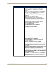
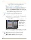
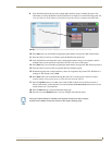
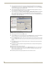
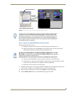
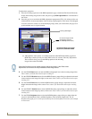
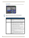
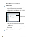
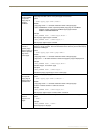
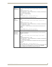
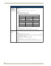
12. Test the incoming wiring by connecting the panel connections to their terminal locations and
applying power. Verify the panel is receiving power and functioning properly before finalizing the
installation.
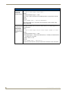
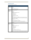
13. Disconnect the terminal end of the power cable from the power supply.
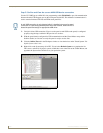
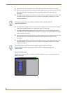
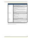
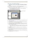
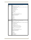
14. Follow the procedures outlined within Steps 1 - 5 on page 42 thru page 43 to carefully reinstall the
LCD panel back into the back box housing.
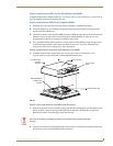
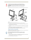
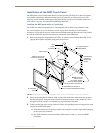
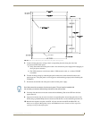
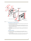
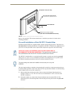
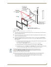
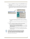
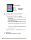
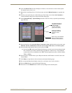
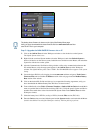
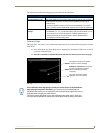
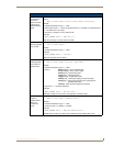
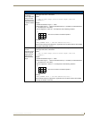
15. Carefully slide the main unit into the cutout until the Mounting Tabs of the NXD-1700VG unit lie
flush against the wall.
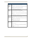
16. Insert and secure the four #6 screws into their corresponding holes located along the sides of the
NXD-1700VG (using a grounded Phillips-head screwdriver) until the unit is secure and flush
against the wall.
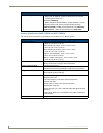
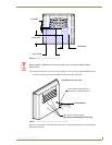
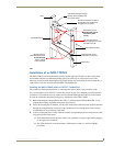
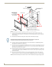
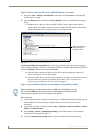
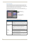
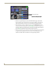
17. Place the magnetic faceplate (A in FIG. 62) back onto the main NXD unit. Make sure to align the
Microphone, Light, and PIR Motion sensor locations to their respective openings on the front
bezel/faceplate.
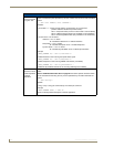
The determining factor in the depth of the cut into the beam is the thickness of the
surface. The MOUNTING TAB MUST BE FLUSH against the surface and therefore,
the depth of the notch depends on that thickness.
Don’t disconnect the connectors from the touch panel. The unit must be installed with
the attached connectors before being inserted into the solid surface.