


Installation Procedures: 12" and 15" Panels
66
VG-Series Modero Touch Panels
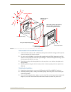
11. Reconnect the terminal RJ-45, Ethernet, USB, and any optional audio/video wiring to their
respective locations on either the NXA-AVB/RGB Breakout Box, Ethernet port, or NetLinx Master.
12. Reconnect the terminal power connector on the 12 VDC-compliant power supply and apply power.
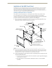
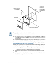
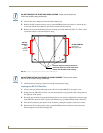
Installing an NXD into an (optional) Rack Mount Kit (NXA-RK12 or NXA-RK15)
1.
Remove the magnetic faceplate/bezel from the main NXD unit by gripping the faceplate and pulling
with gentle outward force.
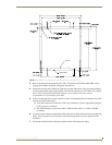
2. Thread the incoming RJ-45, Ethernet, USB, and any optional audio/video wiring through the
opening in the equipment rack (from their terminal locations). Refer to the Wiring Guidelines for
the 1200VG and 1500VG Panels section on page 68 for pinout descriptions. Leave enough slack to
accommodate any re-positioning of the panel.
3. Connect all data and power wiring connectors to their corresponding locations along the side of the
(un-powered) NXD touch panel.
Verify the terminal end of the power cable is not connected to a power supply before plugging
in the 2-pin power connector.
The USB connectors can be from a either a USB extension cable, or a wireless USB RF
transmitter.
4. Test the incoming wiring by connecting the panel connections to their terminal locations and
applying power. Verify the panel is receiving power and functioning properly to prevent repetition
of the installation.
5. Disconnect the terminal end of the power cable from the connected power supply.
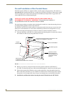
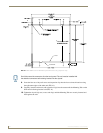
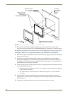
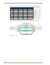
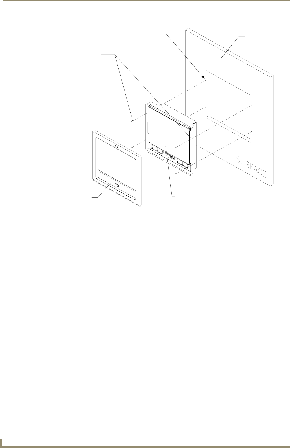
FIG. 45 Wall Mount panel installation configuration for flat/solid surfaces
B - Main NXD unit consists of
Install the four (#4)
mounting screws
into the holes
(screws not included)
Flat surface
(can include a
the touch panel and housing
wall, podium, or
other flat
surface)
A - Faceplate
(bezel)
Attachment is done
along the edges of
the cutout