


Introduction
17
VG-Series Modero Touch Panels
VG-Series Modero Connectors
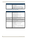
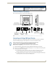
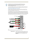
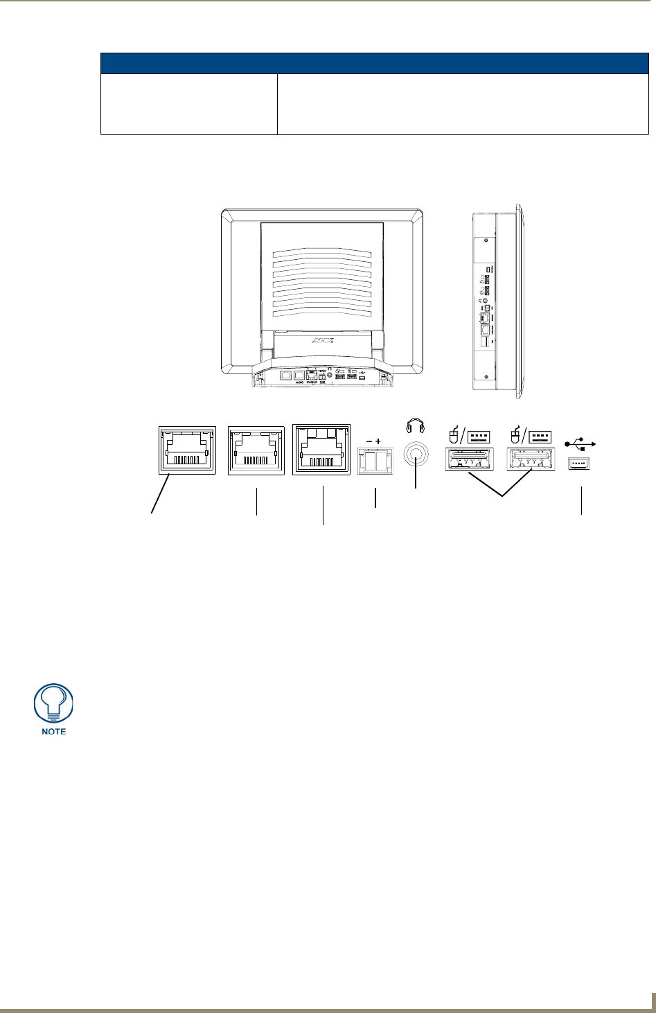
FIG. 1 shows the connectors on the VG-Series Modero panels.
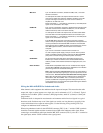
Connecting and Using USB Input Devices
These panels can have up to two USB-capable input devices connected for use both on its different
firmware and TPD4 panel pages. These input devices can consist of a keyboard or mouse.
1. Insert the input device USB connectors into the appropriate USB connector on the panel.
2. Press the on-screen Reboot button (Protected Setup page) to save any changes and restart the panel.
3. After the panel splash-screen disappears:
If a USB mouse has been connected, a mouse cursor appears on the panel screen and its
location corresponds to the mouse cursor position sent by the external USB mouse.
If a USB keyboard has been connected, only on-screen keyboards and keypads will reflect any
external keystrokes sent from the external USB keyboard.
1700VG Panel Specifications (Cont.)
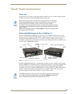
Other AMX Equipment (Cont.): • Upgrade Compact Flash (factory programmed with firmware):
NXA-CFTPV256M - 256 MB V/VG compact flash card (FG2116-43)
NXA-CFTPV512M - 512 MB V/VG compact flash card (FG2116-44)
NXA-CFTPV1G - 1 GB V/VG compact flash card (FG2116-45)
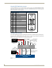
FIG. 1
Connector layout on sample VG-Series Video Touch Panels (RGB connector available with RGB Kit)
RGB
AUDIO/VIDEO
RGB
ETHERNET
A
L
12VDC
PWR
PROGRAM
Stereo
Audio-Video from
Ethernet
Power
NXT VG-Series
rear panel of the base
NXD VG-Series
on left side panel
NXA-AVB/RGB
(CAT5)
Keyboard/Mouse
USB connectors (2)
Mini-USB
(Program Port)
(CAT5)
Composite/RGB
and pass-thru
control (CAT5)
connectors located on
connectors located
Output
USB-connected input devices are detected and recognized by the panel upon
connection. Refer to the Configuring and Using USB with a Virtual
Master section on page 95 for more information on using a USB connection.