


21555 Non-Transparent PCI-to-PCI Bridge User Manual 111
JTAG Test Port 13
This chapter presents the theory of operation information about the 21555 JTAG interface. See Chapter 16 for
specific information about the JTAG registers.
The 21555’s implementation of the JTAG test port is according to IEEE Std. 1149.1, IEEE Standard Test Access
Port and Boundary-Scan Architecture.
The JTAG test port consists of the following:
• A 5-signal test port interface.
• A test access port controller.
• An instruction register.
• A bypass register.
• A boundary-scan register.
13.1 JTAG Signals
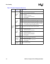
The JTAG test access port is to be used only while the 21555 is not operating. Table 30 describes JTAG signals.
Table 30. JTAG Signals
Signal
Name
Type Description
tck I
JTAG boundary-scan clock. Signal tck is the JTAG logic control clock. This pin has an internal weak pull-down
resistor.
tdi I
JTAG serial data in. Signal tdi is the serial input through which JTAG instructions and test data enter the JTAG
interface. The new data on tdi is sampled on the rising edge of tck. An unterminated tdi is pulled high by a
weak pull-up resistor internal to the device.
tdo O
JTAG serial data out. Signal tdo is the serial output through which test instructions and data from the test logic
leave the 21555.
tms I
The JTAG test mode select pin, tms causes state transitions in the Test Access Port (TAP) controller. The tms
signal is pulled high by a weak pull-up resistor internal to the device. If this pin is low while t_rst_l is low the
device can enter an unsupported mode. Other devices that are not on early power and are connected to the
JTAG Scan Chain, pull tms low during Hot Insertion causing the 21555 to enter the unsupported mode.
During the Hot Insertion isolate this signal from other JTAG devices on the circuit board or JTAG scan chain.
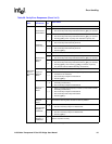
trst_l I
JTAG TAP reset and disable. When low, JTAG is disabled and the TAP controller is asynchronously forced
into the reset state, which in turn asynchronously initializes other test logic. An unterminated trst_l is pulled
high by a weak pull-up resistor internal to the device. The TAP controller must be reset before the JTAG
circuits can function. For normal JTAG TAP port operation, this signal must be high.
Prior to normal 21555 operation, this signal must be strobed low or pulled low with a 1k
Ω resistor.