140 21555 Non-Transparent PCI-to-PCI Bridge User Manual
List of Registers
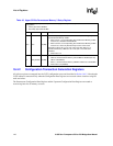
16.4.2 Configuration Transaction Generation Registers
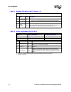
All of these registers are mapped into the 21555 configuration space and described in Section 16.4.2. Note that the
21555 initiates a transaction only when the Configuration Data registers are accessed at these locations using I/O
reads and writes.
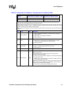
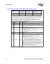
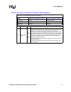
The Downstream Configuration Data Register and the Upstream Configuration Data Register are treated as
reserved registers for all memory accesses.
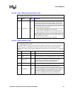
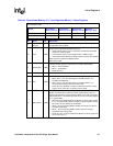
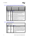
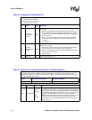
Table 45. Upper 32 Bits Downstream Memory 3 Setup Register
This register may be preloaded by serial ROM or programmed by the local processor before host
configuration.
• Primary byte offset: BF:BCh
• Secondary byte offset: BF:BCh
Bit Name R/W Description
30:0 Size R/(WS)
These bits specify upper 32 bits of the size of the address range requested
by Downstream Memory 3 BAR.
• When a bit is 1, the corresponding bit in Downstream Memory 3 BAR
functions as a readable and writable bit.
• When a bit is 0, the corresponding bit in Downstream Memory 3 BAR
functions as a read
-only bit that always returns 0 when read.
These bits must be set to a non
-zero value only when bits [2:1] of
Downstream Memory 3 BAR are set to 10b (this is not enforced in
hardware).
• Reset value is 0
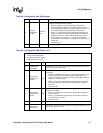
31 BAR_Enable R/(WS)
64
-bit Downstream Memory 3 BAR enable.
• When 0, the Downstream Memory 3 64
-bit BAR is disabled (but may
still be a 32
-bit BAR).
• When 1, the Downstream Memory 3 BAR is enabled as a 64
-bit BAR.
• Reset value is 0 (disabled)


