


21555 Non-Transparent PCI-to-PCI Bridge User Manual 67
Initialization Requirements
The secondary reset output, s_rst_l, is asserted and remains asserted when any of the following are true:
• The 21555 primary reset input, p_rst_l, is asserted.
• The 21555 secondary reset input, s_rst_in_l, is asserted.
• The Secondary Reset bit in the Table 123, “Reset Control Register” on page 188 is set to a 1.
• The Chip Reset bit in the Table 123, “Reset Control Register” on page 188 is set to a 1.
• A power management transition from D3
hot
to D0 occurs (see Section 6.4.1).
A power management transition from D3
hot
to D0 or setting the Chip Reset bit causes the Secondary Reset bit to set
automatically. When set automatically, the Secondary Reset bit also clears automatically and s_rst_l deasserts after
greater than 100
µs following s_rst_l assertion.
Assertion of s_rst_l by setting the secondary reset bit does not cause the 21555 register state to be reset. However,
all the 21555 data buffers are reset.
Note: A configuration write is required to clear the secondary reset bit if the bit is set by a configuration
write. Care must be taken when this bit is asserted from the secondary interface.
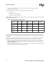
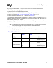
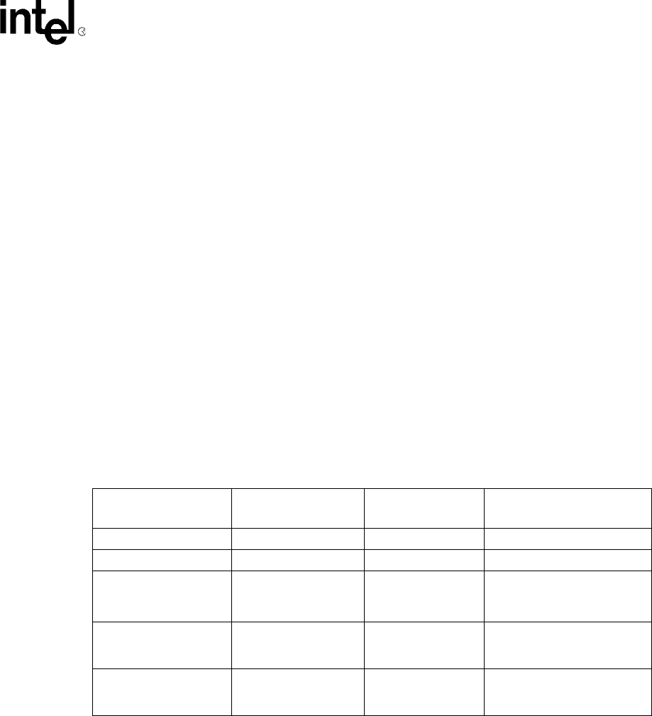
Table 18 summarizes the various 21555 reset mechanisms.
Note: The signal s_rst_l is asserted for all reset mechanisms, but how s_rst_l deasserts and whether the
device is reset varies from case to case.
Table 18. Reset Mechanisms
Reset Mechanism
Reset 21555 Buffers
and State
Assert Secondary
Reset Bit
Deassertion of s_rst_l
p_rst_l Yes No On p_rst_l deassertion
s_rst_in_l Yes No On s_rst_in_l deassertion
Chip Reset Bit set Yes Yes
Automatically after >100 ms
(Secondary Reset bit also
clears automatically)
Secondary Reset Bit set
Reset data buffers and
primary master state
machine
Yes
On clearing of Secondary
Reset bit
Transition from D3
hot
to
D0 (see Section 6.4.1).
Yes Yes
Automatically after >100 ms
(Secondary Reset bit also
clears automatically)