66 21555 Non-Transparent PCI-to-PCI Bridge User Manual
Initialization Requirements
6.2 Reset Behavior
The 21555 implements a primary reset input, p_rst_l, a secondary reset input s_rst_in_l, and a secondary reset
output, s_rst_l. The 21555 also implements a Chip Reset bit and a Secondary Reset bit in the Table 123, “Reset
Control Register” on page 188.
The device is reset when one of the following occurs:
• The signal p_rst_l is asserted.
• The signal s_rst_in_l is asserted.
• The Chip Reset bit is written with a 1.
• A power management transition from D3
hot
to D0 occurs (see Section 6.4.1).
When the Chip Reset bit is written with a 1, the chip reset bit is cleared 7 clocks after it is set. The actual chip reset
signal is internally delayed to allow the configuration cycle to complete normally. Chip reset causes all the register
values to be reset, and all the queues to be cleared. The primary PCI bus and control signals are tristated as long as
either chip reset is occurring or p_rst_l is asserted.
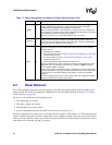
s_pme_l I
Secondary bus power management event. The subsystem asserts this signal to the
21555 to indicate that it is signaling a power management event. The 21555
conditionally asserts p_pme_l when s_pme_l is asserted low.
When the subsystem does not generate power management events, this signal can
also be used for a subsystem status signal. A deasserting (rising) edge on this signal
can conditionally cause the 21555 to assert p_inta_l.
When this signal is not used, it should be tied high with a 1k resistor.
s_rst_in_l I
Alternate reset input for the 21555. Asserting s_rst_in_l is the same as asserting
p_rst_l. These two signals are ORed on the 21555. All configuration modes are
captured on this edge. Signal s_rst_in_l allows for either a reset to be initiated from
the secondary bus or a board reset for a hot-swap.
s_rst_l O
Secondary PCI bus RST#. Signal s_rst_l is driven by the 21555 and acts as the PCI
reset for the secondary bus. The 21555 asserts s_rst_l when any of the following
conditions are met:
• Signal p_rst_l is asserted.
• The secondary reset bit in the Table 123, “Reset Control Register” on page 188 in
configuration space is set.
• The chip reset bit in the Table 123, “Reset Control Register” on page 188 in
configuration space is set.
• Power management transition from D3
hot
to D0 occurs.
When the 21555 asserts s_rst_l, it tristates all secondary control signals and, when
designated as the secondary bus central resource, asserts s_req64_l and drives
zeros on s_ad, s_cbe_l, and s_par.
Signal s_rst_l remains asserted until p_rst_l is deasserted, and the secondary reset
bit is clear. Deassertion of s_rst_l occurs automatically based on internal timers when
s_rst_l assertion is caused by setting the chip reset bit or a power management
transition.
Assertion of s_rst_l by itself does not clear register state, and configuration registers
are still accessible from the primary PCI interface.
Table 17. Power Management, Hot-Swap, and Reset Signals (Sheet 2 of 2)
Signal Name Type Description


