


21555 Non-Transparent PCI-to-PCI Bridge User Manual 131
List of Registers
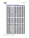
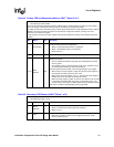
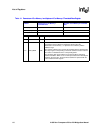
3 Prefetchable R
Indicates whether the region is prefetchable. Accesses to the 21555 registers
are disconnected after the first data phase.
• When 0, nonprefetchable memory is requested.
• When 1, prefetchable memory is requested.
• Reset value is 0
11:4 — R Returns 0 when read.
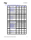
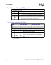
31:12
Base
Address
R/W
These bits indicate the size of the requested address range and set the base
address of the range.
• The low 4 KB of this address range map the 21555 CSRs into primary
memory space.
• The remaining space in this range above 4 KB, if any, specifies a range
for downstream forwarding of memory transactions.
These bits determine the function of the corresponding bit in this register.
• When a bit in the setup register is 0 then the same bit in this register is a
read
-only bit and always returns 0 when read.
• When a bit in the setup register is one (1), the same bit in this register is
writable and returns the value last written when read.
• When the setup register is written to all zeros, the minimum size of 4 KB
is requested (the 21555 CSR access only, no forwarding range). The
maximum size of this range is 2 GB; therefore bit [31] is always writable.
Reset value is 4 KB of nonprefetchable memory requested.
a. See Chapter 4, “Address Decoding” for more information.
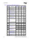
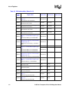
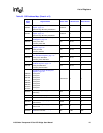
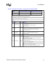
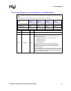
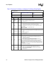
Table 35. Secondary CSR Memory BARs
a
(Sheet 1 of 2)
• Primary byte offset: 53:50h
• Secondary byte offset: 13:10h
Bit Name R/W Description
0
Space
Indicator
R
Indicates the type of address space requested.
• When a 0, indicate that memory space is requested.
• When a one (1),
2:1 Type R
Indicates size and location of the 21555 memory mapped registers.
• When 00, the 21555 registers can be mapped anywhere in 32
-bit
memory address space.
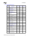
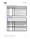
Table 34. Primary CSR and Downstream Memory 0 Bar
a
(Sheet 2 of 2)
• Primary byte offset: 13:10h
• Secondary byte offset: 53:50h
The Primary CSR and Downstream Memory 0 BARs map the 21555 registers into primary memory space.
They can specify a downstream memory range for forwarding of memory transactions.
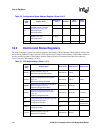
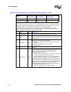
To specify a downstream forwarding range, load the Downstream Memory 0 Setup Register from the optional
SROM or the local processor This load must occur before configuration software running on the host
processor can access this register.
Local processor access of the setup register should be done before the Primary Lockout Reset Value bit is
cleared.
Bit Name R/W Description