


182 21555 Non-Transparent PCI-to-PCI Bridge User Manual
List of Registers
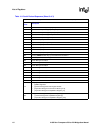
2Bh Upstream I/O or Memory 0 Setup [31:24]
2Ch Upstream Memory 1 Setup [7:0]. Bits [0, 7:4] are not loaded and should be 0.
2Dh Upstream Memory 1 Setup [15:8]. Bits [11:8] are not loaded and should be 0.
2Eh Upstream Memory 1 Setup [23:16]
2Fh Upstream Memory 1 Setup [31:24]
30h Chip Control 0 [7:0]
31h Chip Control 0 [15:8]. Bits [13:12] are not loaded and should be 0.
32h Chip Control 1 [7:0]
33h Chip Control 1 [15:8]
34h Arbiter Control [7:0]
35h Arbiter Control [15:7]. Bits [15:10] are not loaded and should be 0.
36h Primary SERR# Disable. Bit [7] is not loaded and should be 0.
37h Secondary SERR# Disable. it [7] is not loaded and should be 0.
38h Power Management Data 0
39h Power Management Data 1
3Ah Power Management Data 2
3Bh Power Management Data 3
3Ch Power Management Data 4
3Dh Power Management Data 5
3Eh Power Management Data 6
3Fh Power Management Data 7
40h Reserved
41h
• [1:0] 00b (Reserved)
• [2] BiST Supported
• [3] Power Management Data Register Enable
• [5:4] Power Management Control and Status [14:13]
• [7:6] Power Management Capabilities Register [1:0]
42h
• [0] Power Management Capabilities Register [2]
• [1] Power Management Capabilities Register [5]
• [7:2] Power Management Capabilities Register [14:9]
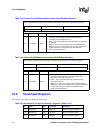
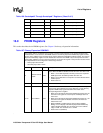
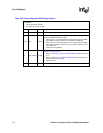
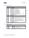
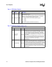
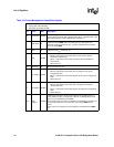
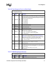
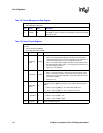
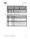
Table 114. Serial Preload Sequence (Sheet 3 of 3)
Not all of the bits in the sequence are used. Bits that are not used must be 0 (zero)
Byte
offset
Description