21555 Non-Transparent PCI-to-PCI Bridge User Manual 35
Address Decoding
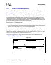
4.3.1 Using the BAR Setup Registers
All downstream and upstream BARs have programmable sizes, and can be disabled so that they request no space.
The Primary CSR and Downstream Memory 0 BAR cannot be totally disabled, as the 21555 CSRs are always
mapped in the bottom 4KB. The forwarding part of the range can be disabled by requesting only 4KB of memory
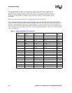
Table 12 on page 47 summarizes the minimum and maximum range for each address range). In addition, the
Downstream Memory 3 BAR can be configured to be mapped in 64-bit address space. The register then comprises
two 32-bit registers and can be used for forwarding DACs downstream. 64-bit addressing support is discussed
further in Section 4.3.5 on page 41. These BARs can also be programmed to be prefetchable or non-prefetchable.
Programming of all the forwarding BARs with the exception of the Upstream Memory 2 BAR is done through
corresponding device-specific Setup configuration registers. The Primary Expansion ROM BAR also has a Setup
register. Setup registers are preloaded by the serial ROM and can also be written from the secondary interface. Each
bit of the Setup register corresponds to the same bit of its respective BAR.
Bit 0 of the Downstream I/O or Memory 1 Setup register and Upstream I/O or Memory 0 Setup register (see
Section 16 on page 121) should be written with:
• A zero (0) to select a memory BAR.
• A one (1) to select an I/O BAR. Bits [2:1] are writable to select the type of memory mapping. The Downstream
Memory 3 Setup registers bits [2:1] may be set to 10b to select 64-bit addressing.
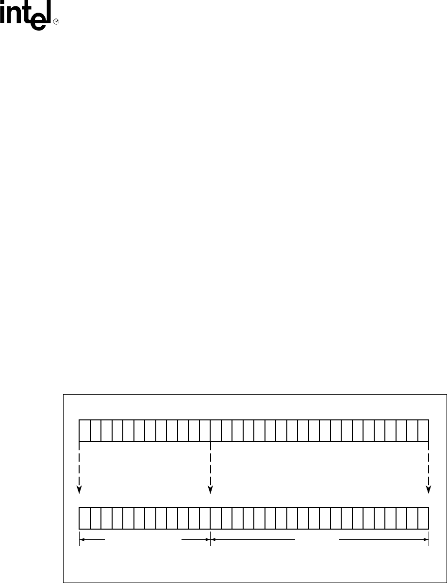
A mask is used to set the size of the BAR for the remaining read/write bits of the Setup register. Writing a 1 sets the
corresponding bit in that Setup register’s BAR to be read/write. Writing a 0 (zero) sets the corresponding bit in that
Setup register’s BAR to be read only as 0. Therefore, the size is set by writing the appropriate number of most
significant bits to a 1, and the remaining bits to a 0. When all of the zeros and ones in the size field are not
contiguous, this is illegal and unpredictable results may occur. When the most significant writable bit of the Setup
register is a 0, the corresponding BAR is disabled and requests no space.
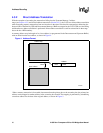
Figure 3 shows an example of using a Setup register to program a BAR to request 1 MB of memory space.
Figure 3. BAR Setup Register Example
A7461-01
bbbbbb
R/W (Base Address)
Setup Register
Base Address Register
Read Only
bbbbbb
111111111111
000000000000000010
0
01
0000000000000001001
31 20 19
20 19
0
31 0


