


84 21555 Non-Transparent PCI-to-PCI Bridge User Manual
Parallel ROM Interface
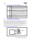
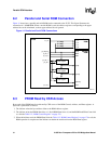
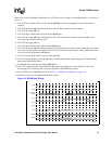
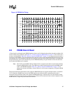
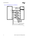
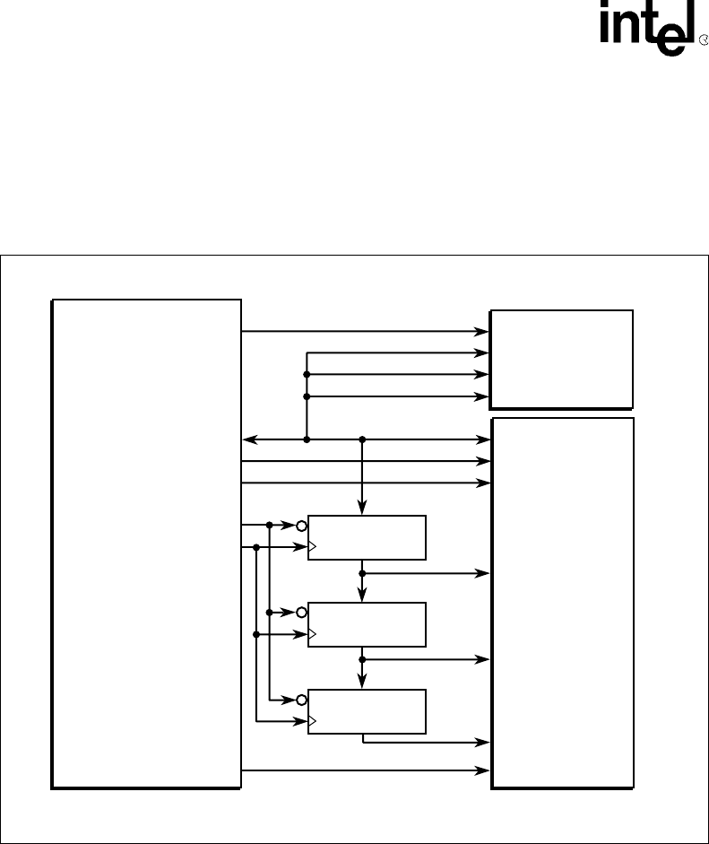
8.2 Parallel and Serial ROM Connection
Figure 14 shows how a parallel and serial ROM can be connected to the 21555. This figure illustrates the
connection of a 16MB ROM. When a smaller ROM is used, the address registers corresponding to the upper
address bits can be eliminated, as those upper address bits are ignored.
.
8.3 PROM Read by CSR Access
Byte reads of the PROM may be performed by CSR access of the ROM Control, Address, and Data registers. A
byte read is performed as follows:
1. The initiator writes the byte address offset to the ROM Address register.
2. The initiator writes the PROM Start bit to a 1, Serial ROM Start bit to a 0, and the ROM Read/Write Control bit
to a 0 in the Table 112, “ROM Control Register” on page 178.
3. When the initiator reads the PROM Start bit in the Table 112, “ROM Control Register” on page 178 as a 0, the
ROM operation is complete and the initiator can obtain the read data from the ROM Data register.
Figure 14. Parallel and Serial ROM Connections
A7491-01
pr_ad[2]
pr_ad[1]
pr_ad[0]
en
en
en
8-bit register
8-bit register
8-bit register
21555
Serial
ROM
Parallel
ROM
pr_ad[7:0]
pr_wr_l
pr_rd_l
pr_cs_l
sr_cs
pr_ale_l
pr_clk
sr_cs
sr_ck
sr_di
sr_do
a[23:16]
a[15.8]
a[7:0]
OE#
WE#
d[7:0]
CE#