21555 Non-Transparent PCI-to-PCI Bridge User Manual 149
List of Registers
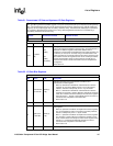
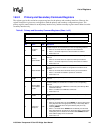
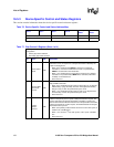
16.5.2 Primary and Secondary Command Registers
The register types in this section have separate registers for the primary and secondary interfaces. However, the
register description is given once, and applies to both the primary and secondary configuration registers. The
primary register controls behavior on the primary interface only, and the secondary register controls behavior on the
secondary interface only.
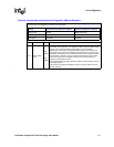
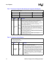
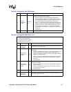
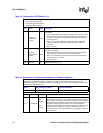
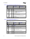
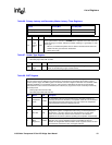
Table 61. Primary and Secondary Command Registers (Sheet 1 of 2)
Bit Name R/W Description
0
I/O Space
Enable
R/W
Controls response to I/O transactions on the corresponding interface.
• When 0, the 21555 does not respond to I/O transactions.
• When 1, the 21555 response to I/O transactions is enabled.
• Reset value is 0
1
Memory
Space Enable
R/W
Controls response to memory transactions on the corresponding
interface.
• When 0, the 21555 does not respond to memory transactions.
• When 1, the 21555 response to memory transactions is enabled.
• Reset value is 0.
2 Master Enable R/W
Controls 21555's ability to initiate memory and I/O transactions on the
corresponding interface. Initiation of configuration transactions is not
affected.
• When 0, the 21555 does not initiate memory or I/O transactions.
• When 1, the 21555 is enabled to operate as an initiator.
• Reset value is 0.
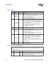
3
Special Cycle
Enable
R
The 21555 ignores special cycle transactions, so this bit is read only and
returns 0.
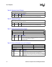
4
Memory Write
and Invalidate
Enable
R/W
This bit controls the ability of the 21555 to generate Memory Write and
Invalidate (MWI) bus commands as a master on the corresponding
interface.
• When 0, Disables use of MWI bus commands (uses Memory Write
commands instead).
• When 1, Enables use of MWI bus commands.
• Reset value is 0
5
VGA Snoop
Enable
R
Reads only as 0 to indicate the 21555 does not respond to VGA palette
writes.
6
Parity Error
Response
R/W
Controls the response of the 21555 when a parity error is detected on the
corresponding interface.
• When 0, the 21555 does not assert PERR#, nor does it set the Data
Parity Reported bit in the appropriate Primary or Secondary Status
registers. The 21555 does not report address parity errors by
asserting SERR#.
• When 1, the 21555 drives PERR# and conditionally sets the Data
Parity Reported bit in the Primary or Secondary Status register when
a data parity error is detected. The 21555 allows SERR# assertion
when address parity errors are detected.
• Reset value is 0.
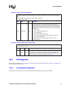
Offsets Primary Command Secondary Command
Primary byte 05:04h 45:44h
Secondary byte 45:44h 05:04h


