21555 Non-Transparent PCI-to-PCI Bridge User Manual 69
Initialization Requirements
6.3.1 With SROM, Local, and Host Processors
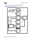
The following is the 21555 initialization procedure using all configuration mechanisms:
1. Serial Preload
Upon deassertion of p_rst_l or completion of chip reset, the 21555 automatically starts the serial load
sequence when a SROM is present. The serial load takes approximately 18700 primary bus clock (p_clk)
cycles (550 SROM clock cycles). During this time, the 21555 returns a target retry to any configuration
transaction access from either interface.
The serial load can overwrite selected PCI read-only registers, program forwarding BAR types and sizes,
and configure device-specific configuration registers.
2. Local Processor Initialization
When the serial load is complete, the 21555 configuration registers are now accessible by the local
processor from the secondary interface.
When the Primary Lockout Reset Value bit is set, the 21555 continues to return target retry to any
configuration accesses from the primary interface (with the exception of the Reset Control configuration
register at offset D8h). The local processor can write selected locations that are loadable from the SROM,
and therefore can be used to change parameters loaded during SROM preconfiguration. The local
processor can also perform standard PCI configuration of the secondary interface configuration registers.
Once the base address registers are mapped and the secondary enables set, the 21555 may accept memory
or I/O transactions to its CSR registers.
When local processor initialization is complete, the local processor should clear the Primary Lockout
Reset Value bit to allow host initialization. When the Primary Lockout Reset Value bit is clear after serial
preload, the host processor and local processor can access the 21555 concurrently immediately after serial
preload is complete. The local processor should not change any primary interface preload values that can
affect host configuration.
This mode of initialization is not recommended unless special care is taken that registers are accessed and
initialized in their proper sequence.
3. Host Initialization
After the serial preload and Primary Lockout Reset Value bit is clear, the host may perform the standard
PCI device configuration. Device-specific expansion ROM code can be accessed through the Primary
Expansion ROM Base Address register.
4. Normal Operation
6.3.2 Without Serial Preload
A SROM is supported, but not required, for the 21555 preinitialization. In the case where a SROM is not connected
to the 21555 or when the first data bits read does not contain 10b, the 21555 terminates the SROM read and
configuration space is then available for local processor configuration. The
Primary Lockout Reset Value bit can
be set to a 1 by pulling pr_ad[3] high during chip reset. All primary bus configuration accesses (with the exception
of location D8h) then receive target retry until the local processor clears the
Primary Lockout Reset Value bit.
The local processor first must preconfigure registers that would have been preloaded by the SROM. This is
particularly true of the size and types of the base address registers for forwarding transactions, which upon
completion of reset are disabled and request no address space.
Once the local processor preconfigures the necessary registers, normal PCI configuration of the
secondary configuration registers can proceed. The local processor then must clear the Primary
Lockout Reset Value bit to allow access from the primary bus, unless the Primary Lockout Reset
Value reset value was designated to be low by pulling pr_ad[3] low during reset.


