


5-9
Cisco Intrusion Prevention System Appliance and Module Installation Guide for IPS 7.1
OL-24002-01
Chapter 5 Installing the IPS 4270-20
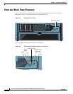
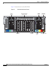
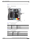
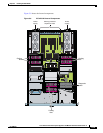
Front and Back Panel Features
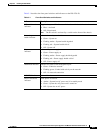
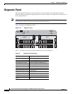
Table 5-1 describes the front panel switches and indicators on the IPS 4270-20.
Table 5-1 Front Panel Switches and Indicators
Indicator Description
UID switch and
indicator
Toggles the system ID indicator, which assists with chassis location in a rack:
•
Blue—Activated
•
Off—Deactivated
Note
The ID switch is activated by a switch on the front of the chassis.
Internal system
health indicator
Indicates internal system health:
•
Green—System on
•
Flashing amber—System health degraded
•
Flashing red—System health critical
•
Off—System off
Power status
indicator
Indicates the power supply status:
•
Green—Power supply on
•
Flashing amber—Power supply health degraded
•
Flashing red—Power supply health critical
•
Off—Power supply off
MGMT0/0 indicator Indicates the status of the management port:
•
Green—Linked to network
•
Flashing green—Linked with activity on the network
•
Off—No network connection
MGMT0/1 indicator Reserved for future use
Power switch and
indicator
Turns power on and off:
•
Amber—System has AC power and is in standby mode
•
Green—System has AC power and is turned on
•
Off—System has no AC power