


4-21
Cisco Intrusion Prevention System Appliance and Module Installation Guide for IPS 7.1
OL-24002-01
Chapter 4 Installing the IPS 4260
Installing and Removing Interface Cards
Step 11
Power on the IPS 4260.
For More Information
•
For the IDM procedure for resetting the IPS 4260, refer to Rebooting the Sensor; for the IME
procedure for resetting the IPS 4260, refer to Rebooting the Sensor.
•
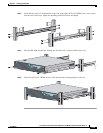
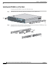
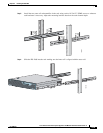
For the procedure for removing the IPS 4260 from a rack, see Rack Mounting, page 4-10.
•
For more information on ESD-controlled environments, see Safety Recommendations, page 2-2.
•
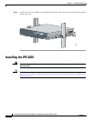
If you are reinstalling the IPS 4260 in a rack, see Rack Mounting, page 4-10.
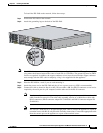
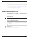
Installing and Removing Interface Cards
The IPS 4260 has 6 expansion card slots, three full-height and three half-height slots. You can install the
optional network interface cards in the two top full-height slots, slots 2 and 3. IPS 4260 supports up to
two network interface cards.
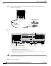
Note
The IPS 4260 supports only one 10GE fiber interface card, which you can install in either of the
supported slots (slots 2 and 3).
Note
We recommend that you install the 4GE bypass interface card in slot 2 if you are installing only one 4GE
bypass card. This improves accessibility to the RJ45 cable connectors.
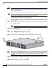
To install and remove interface cards, follow these steps:
Step 1
Log in to the CLI.
Step 2
Prepare the IPS 4260 to be powered off. Wait for the power down message before continuing with Step 3.
sensor# reset powerdown
Note
You can also power off IPS 4260 using the IDM or IME.
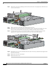
Step 3
Power off the IPS 4260.
Step 4
Remove the power cable and other cables from the IPS 4260.
Step 5
If rack-mounted, remove the IPS 4260 from the rack.
Step 6
Make sure the IPS 4260 is in an ESD-controlled environment.
Step 7
Remove the chassis cover.