


6-14
Cisco Intrusion Prevention System Appliance and Module Installation Guide for IPS 7.1
OL-24002-01
Chapter 6 Installing the IPS 4345 and IPS 4360
Installing the Appliance on the Network
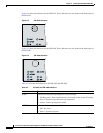
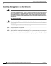
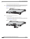
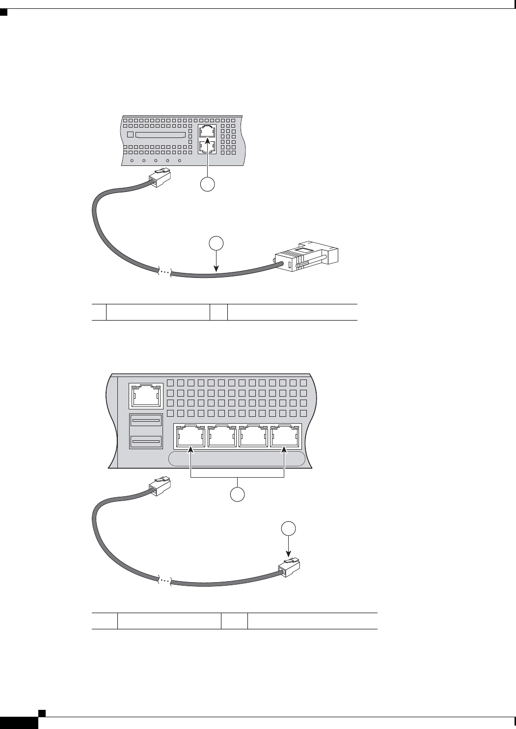
Step 5
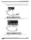
Connect to the console port. The console cable has a DB-9 connector on one end for the serial port on
your computer, and the other end is an RJ-45 connector. Connect the RJ-45 connector to the console port
on the appliance, and connect the other end of the cable, the DB-9 connector, to the console port on your
computer.
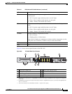
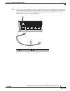
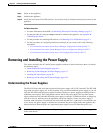
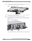
Step 6
Connect to the Ethernet ports. Connect the RJ-45 connector to the Ethernet port and connect the other
end of the RJ-45 connector to your network device, such as a router, switch, or hub.
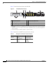
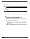
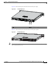
Step 7
Attach the power cable to the appliance and plug the other end in to a power source (a UPS is
recommended).
1 RJ-45 console port 2 RJ-45 to DB-9 console cable
1 RJ-45 Ethernet ports 2 RJ-45 connector
126982
FLASH
CONSOLE
AUX
POWER
STATUS
FLASH
VPN
ACTIVE
2
1
USB2
USB1
LNK SPD
3
LNK SPD
2
LNK SPD
1
LNK SPD
0
MGMT
92685
2
1