


B-11
Cisco Intrusion Prevention System Appliance and Module Installation Guide for IPS 7.1
OL-24002-01
Appendix B Initializing the Sensor
Advanced Setup
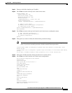
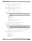
Step 21
Enter
4
to add inline interface pair NewPair.
Step 22
Press Enter to return to the top-level virtual sensor menu.
Virtual Sensor: vs0
Anomaly Detection: ad0
Event Action Rules: rules0
Signature Definitions: sig0
Inline Vlan Pair:
GigabitEthernet0/0:1 (Vlans: 200, 300)
Inline Interface Pair:
newPair (GigabitEthernet0/1, GigabitEthernet0/2)
[1] Remove virtual sensor.
[2] Modify "vs0" virtual sensor configuration.
[3] Create new virtual sensor.
Option: GigabitEthernet0/1, GigabitEthernet0/2)
Add Interface:
Step 23
Press Enter to return to the top-level interface and virtual sensor configuration menu.
[1] Edit Interface Configuration
[2] Edit Virtual Sensor Configuration
[3] Display configuration
Option:
Step 24
Enter
yes
if you want to modify the default threat prevention settings.
Note
The sensor comes with a built-in override to add the deny packet event action to high risk rating
alerts. If you do not want this protection, disable automatic threat prevention.
Virtual sensor newVs is configured to prevent high risk threats in inline mode. (Risk
Rating 90-100)
Virtual sensor vs0 is configured to prevent high risk threats in inline mode.(Risk Rating
90-100)
Do you want to disable automatic threat prevention on all virtual sensors?[no]:
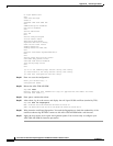
Step 25
Enter
yes
to disable automatic threat prevention on all virtual sensors.
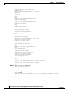
Step 26
Press Enter to exit the interface and virtual sensor configuration.
The following configuration was entered.
service host
network-settings
host-ip 192.168.1.2/24,192.168.1.1
host-name sensor
telnet-option disabled
ftp-timeout 300
no login-banner-text
exit
time-zone-settings
offset 0
standard-time-zone-name UTC
exit
summertime-option disabled
ntp-option disabled
exit
service web-server
port 342
exit
service interface
physical-interfaces GigabitEthernet0/0
admin-state enabled