


6-21
Cisco Intrusion Prevention System Appliance and Module Installation Guide for IPS 7.1
OL-24002-01
Chapter 6 Installing the IPS 4345 and IPS 4360
Removing and Installing the Power Supply
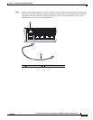
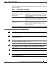
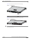
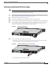
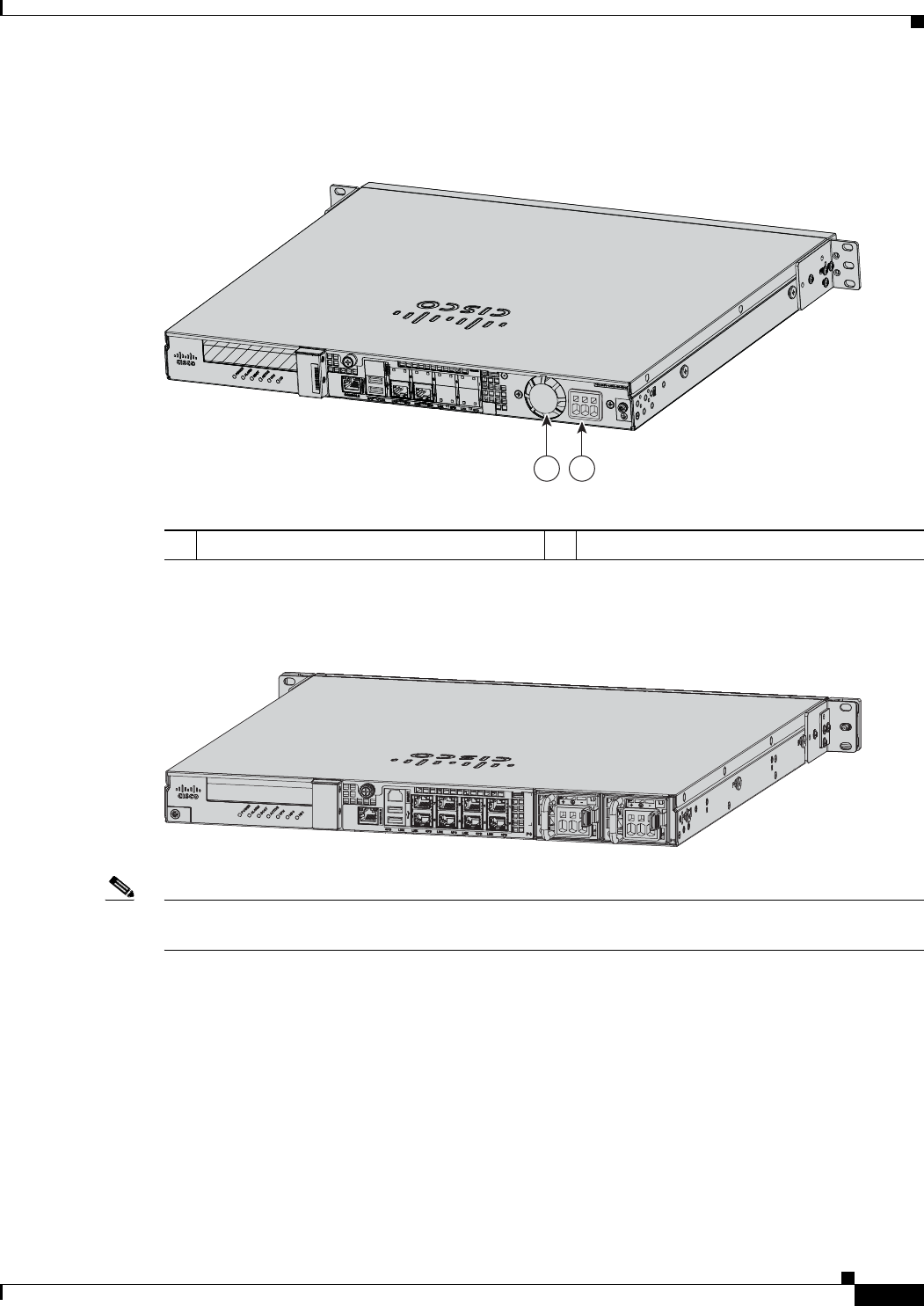
Figure 6-16 shows the back panel of the IPS 4345 with the DC power supply.
Figure 6-16 IPS 4345 Back Panel
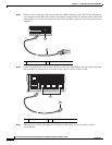
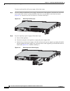
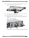
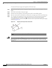
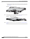
Figure 6-17 shows the back panel of the IPS 4360 with two DC power supplies.
Figure 6-17 IPS 4360 Back Panel
Note
If only one power supply is installed, make sure that it is installed in slot 0 (left slot) and that slot 1 (right
slot) is covered with a slot cover.
1 Fixed fan 2 Fixed DC power supply
333226
1 2
333059