


7-6
Cisco Intrusion Prevention System Appliance and Module Installation Guide for IPS 7.1
OL-24002-01
Chapter 7 Installing the IPS 4510 and IPS 4520
Front and Back Panel Features
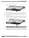
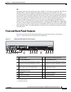
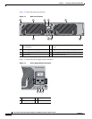
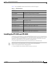
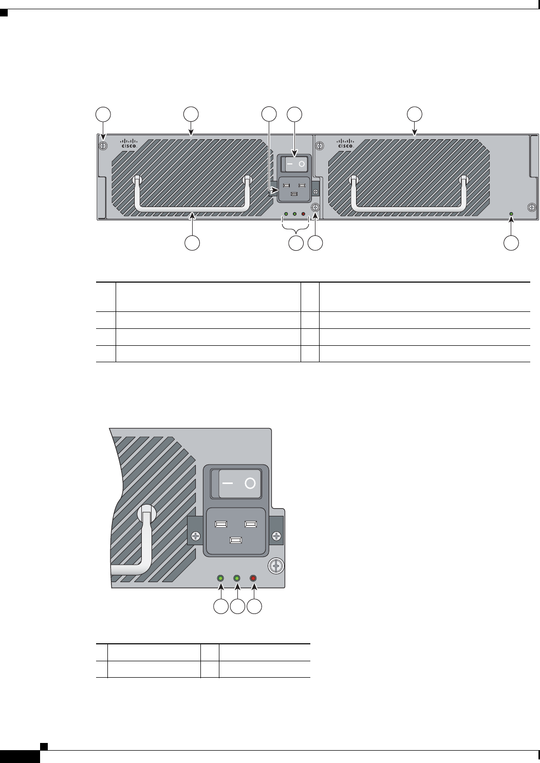
Figure 7-3 shows the back panel features.
Figure 7-3 Back Panel Features
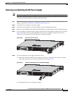
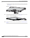
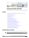
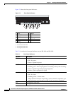
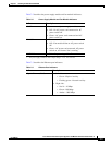
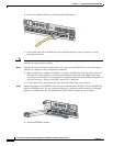
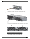
Figure 7-4 shows the power supply module indicators.
Figure 7-4 Power Supply Module Indicators
1 Power supply module (corresponds to
PS1 indicator)
2 Power supply module/fan module removal
screws
3 Power supply module plug 4 Toggle On/Off switch for power supply module
5 Power supply module indicators 6 Power supply module or fan module handle
7 Fan module 8 Fan module indicator
Cisco ASA 1200W AC
100-240V
15.0/8.0.A
56/60Hz
IN
OK
FAN
OK
OUT
FAIL
Cisco-ASA-FAN
2
4
3
5
6 2
1 7
8
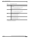
1 IN OK 2 FAN OK
3 OUT FAIL
Cisco ASA 1200W AC
100-240V
15.0/8.0.A
56/60Hz
IN
OK
FAN
OK
OUT
FAIL
253905
1 2 3