


B-18
Cisco Intrusion Prevention System Appliance and Module Installation Guide for IPS 7.1
OL-24002-01
Appendix B Initializing the Sensor
Advanced Setup
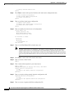
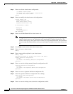
[1] Modify interface default-vlan.
Option:
Step 8
Press Enter to return to the top-level interface and virtual sensor configuration menu.
[1] Edit Interface Configuration
[2] Edit Virtual Sensor Configuration
[3] Display configuration
Option:
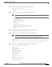
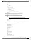
Step 9
Enter
2
to edit the virtual sensor configuration.
[1] Remove virtual sensor.
[2] Modify "vs0" virtual sensor configuration.
[3] Create new virtual sensor.
Option:
Step 10
Enter
2
to modify the virtual sensor vs0 configuration.
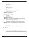
Virtual Sensor: vs0
Anomaly Detection: ad0
Event Action Rules: rules0
Signature Definitions: sig0
No Interfaces to remove.
Unassigned:
Monitored:
[1] PortChannel 0/0
Add Interface:
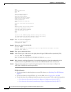
Step 11
Enter
1
to add PortChannel 0/0 to virtual sensor vs0.
Note
Multiple virtual sensors are supported. The adaptive security appliance can direct packets to
specific virtual sensors or can send packets to be monitored by a default virtual sensor. The
default virtual sensor is the virtual sensor to which you assign PortChannel 0/0. We recommend
that you assign PortChannel 0/0 to vs0, but you can assign it to another virtual sensor if you want
to.
Step 12
Press Enter to return to the main virtual sensor menu.
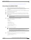
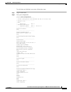
Step 13
Enter
3
to create a virtual sensor.
Name[]:
Step 14
Enter a name and description for your virtual sensor.
Name[]: newVs
Description[Created via setup by user cisco]: New Sensor
Anomaly Detection Configuration
[1] ad0
[2] Create a new anomaly detection configuration
Option[2]:
Step 15
Enter
1
to use the existing anomaly-detection configuration, ad0.
Signature Definition Configuration
[1] sig0
[2] Create a new signature definition configuration
Option[2]:
Step 16
Enter
2
to create a signature-definition configuration file.