


6-7
Cisco Intrusion Prevention System Appliance and Module Installation Guide for IPS 7.1
OL-24002-01
Chapter 6 Installing the IPS 4345 and IPS 4360
Front and Back Panel Features
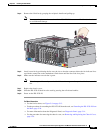
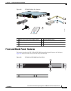
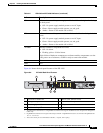
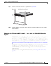
Figure 6-6 shows the back panel features of the IPS 4345.
Figure 6-6 IPS 4345 Back Panel Features
PS1 Indicates the state of the power supply module installed on the right when facing
the back panel:
•
Off—No power supply module present or no AC input.
•
Green—Power supply module present, on, and good.
•
Amber—Power or fan module off or failed.
PS0 Indicates the state of the power module installed on the left when facing the back
panel:
•
Off—No power supply module present or no AC input.
•
Green—Power supply module present, on, and good.
•
Amber—Power or fan module off or failed.
ALARM Indicates whether a component has failed:
•
Off—No alarm.
•
Flashing yellow—Critical alarm.
Major failure of hardware component or software module, temperature over the
limit, power out of tolerance, or OIR is ready to remove the module.
HD1 N/A
HD2 N/A
Table 6-2 IPS 4345 and IPS 4360 Indicators (continued)
Indicator Description
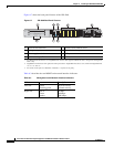
1 Reserved for future use 2 Chassis cover removal screw
3 Management port
1
1. The Management 0/0 interface is a GigabitEthernet interface that supports FastEthernet and is designed for management
traffic only.
4 Network interface ports
2
2. GigabitEthernet interfaces from right to left and top to bottom—GigabitEthernet 0/0, 0/1, 0/2, and 0/3 and Gigabitethernet
1/0, 1/1, 1/2, and 1/3.
5 Power supply module 6 USB ports
7 Serial console port
3
3. The serial console port uses 9600 baud, 8 data bits, 1 stop bit, and no parity.
8 Indicators
POWER
ALARM
BOOT
ACTIVE
VPN
HD0
334531
2 51 3
678
4