


1-17
Cisco Intrusion Prevention System Appliance and Module Installation Guide for IPS 7.1
OL-24002-01
Chapter 1 Introducing the Sensor
How the Sensor Functions
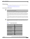
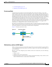
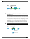
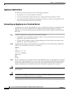
Figure 1-3 illustrates inline interface pair mode:
Figure 1-3 Inline Interface Pair Mode
Inline VLAN Pair Mode
Note
The ASA IPS modules (,ASA 5500 AIP SSM, ASA 5500-X IPS SSP, and ASA 5585-X IPS SSP) do not
support inline VLAN pairs.
You can associate VLANs in pairs on a physical interface. This is known as inline VLAN pair mode.
Packets received on one of the paired VLANs are analyzed and then forwarded to the other VLAN in the
pair.
Inline VLAN pair mode is an active sensing mode where a sensing interface acts as an 802.1q trunk port,
and the sensor performs VLAN bridging between pairs of VLANs on the trunk. The sensor inspects the
traffic it receives on each VLAN in each pair, and can either forward the packets on the other VLAN in
the pair, or drop the packet if an intrusion attempt is detected. You can configure an IPS sensor to
simultaneously bridge up to 255 VLAN pairs on each sensing interface. The sensor replaces the
VLAN ID field in the 802.1q header of each received packet with the ID of the egress VLAN on which
the sensor forwards the packet. The sensor drops all packets received on any VLANs that are not
assigned to inline VLAN pairs.
Note
You cannot use the default VLAN as one of the paired VLANs in an inline VLAN pair.
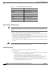
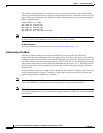
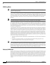
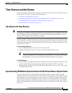
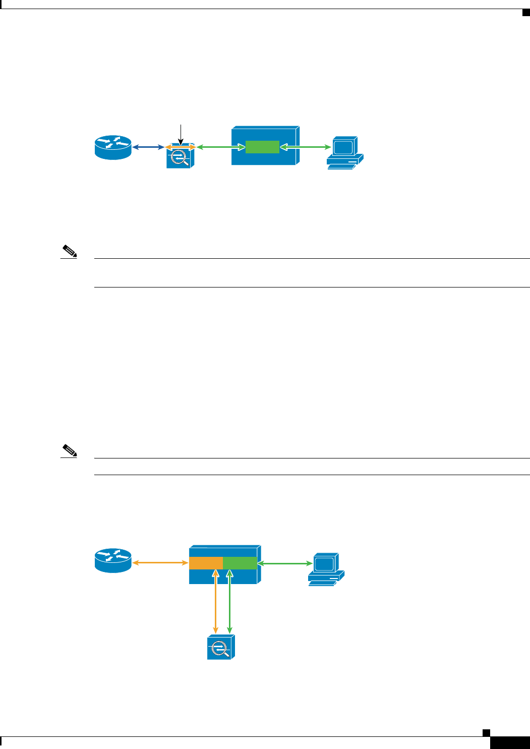
Figure 1-4 illustrates inline VLAN pair mode:
Figure 1-4 Inline VLAN Pair Mode
Host
Sensor
Switch
Traffic passes
through interface pair
253444
Router
VLAN A
Host
Sensor
Switch
253445
Router
VLAN B
VLAN A
Pairing VLAN A and B
Trunk port carrying
VLAN A and B