


3-12
Cisco Intrusion Prevention System Appliance and Module Installation Guide for IPS 7.1
OL-24002-01
Chapter 3 Installing the IPS 4240 and IPS 4255
Installing the IPS 4240-DC
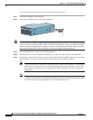
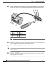
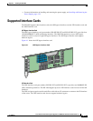
Step 9
Insert the ground wire into the connector for the earth ground and tighten the screw on the connector.
Using the same method as for the ground wire, connect the negative wire and then the positive wire.
Note
The DC return connection to this system is to remain isolated from the system frame and chassis.
Step 10
After wiring the DC power supply, remove the tape from the circuit breaker switch handle and reinstate
power by moving the handle of the circuit breaker to the ON position.
Step 11
Replace the DC power supply plastic shield.
Step 12
Power on the IPS 4240-DC from the switch at the back of the chassis.
Note
If you need to power cycle the IPS 4240-DC, wait at least 5 seconds between powering it off and
powering it back on.
Step 13
Initialize the IPS 4240-DC.
Step 14
Upgrade the IPS 4240-DC with the most recent Cisco IPS software. You are now ready to configure
intrusion prevention on the appliance.
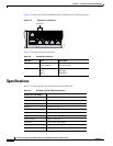
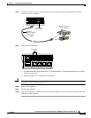
1 Negative 5 Negative
2 Positive 6 Positive
3 Ground 7 Ground
4 On/Off Switch
+ –
+ –
148405
5
6
7
1
4
3
2