


3-3
Cisco Intrusion Prevention System Appliance and Module Installation Guide for IPS 7.1
OL-24002-01
Chapter 3 Installing the IPS 4240 and IPS 4255
Front and Back Panel Features
Front and Back Panel Features
Note
Although the graphics shows the IPS 4240, the IPS 4255 has the same front and back panel features and
indicators.
This section describes the IPS 4240 and IPS 4255 front and back panel features and indicators.
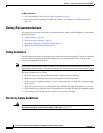
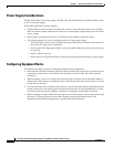
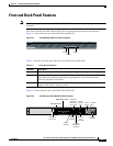
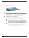
Figure 3-1 shows the front view of the IPS 4240 and IPS 4255.
Figure 3-1 IPS 4240/IPS 4255 Front Panel Features
Table 3-1 describes the front panel indicators on the IPS 4240 and IPS 4255.
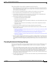
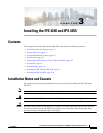
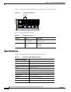
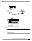
Figure 3-2 shows the back view of the IPS 4240 and IPS 4255.
Figure 3-2 IPS 4240 and IPS 4255 Back Panel Features
114003
PWR STATUS FLASH
Cisco IPS 4240 series
Intrusion Prevention Sensor
Power
Flash
Status
Table 3-1 Front Panel Indicators
Indicator Description
Power Off indicates no power. Green when the power supply is running.
Status Blinks green while the power-up diagnostics are running or the system is booting. Solid
green when the system has passed power-up diagnostics. Solid amber when the
power-up diagnostics have failed.
Flash Off when the compact flash device is not being accessed. Blinks green when the
compact flash device is being accessed.
114002
LINK SPD
2
LINK SPD
1
LINK SPD
0
LINK SPD
3
MGMT
USB2
USB1
FLASH
CONSOLE
AUX
POWER
STATUS
FLASH
Power
connector
Power
switch
Indicator
light
Auxiliary
port
(not used)
Serial
console
port
External
compact
flash device
(not used)
Compact
flash device
indicator
Status
indicator
Power
indicator
GigabitEthernet0/0
USB ports
(not used)
Management0/0