


6-24
Cisco Intrusion Prevention System Appliance and Module Installation Guide for IPS 7.1
OL-24002-01
Chapter 6 Installing the IPS 4345 and IPS 4360
Removing and Installing the Power Supply
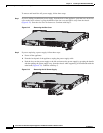
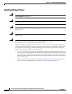
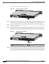
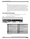
Figure 6-20 shows the DC power supply with lead wires.
Figure 6-20 DC Power Supply with Lead Wires
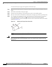
Step 7
Insert the exposed end of one of the ground wires into the inlet on the DC power supply. After you push
in the wires, they are held in place with a spring, which makes the physical contact. Make sure that you
cannot see any wire lead. Only wires with insulation should extend from the DC power supply.
Step 8
Repeat Step 5 through Step 7 for the remaining two DC input power source wires, the positive lead wire
and the negative lead wire.
Step 9
Use a tie wrap to secure the wires coming from the power supply to the rack so that the wires cannot be
pulled from the power supply by casual contact. Make sure the tie wrap allows for some slack in the
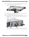
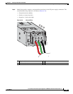
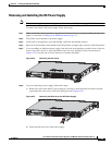
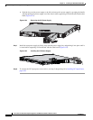
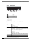
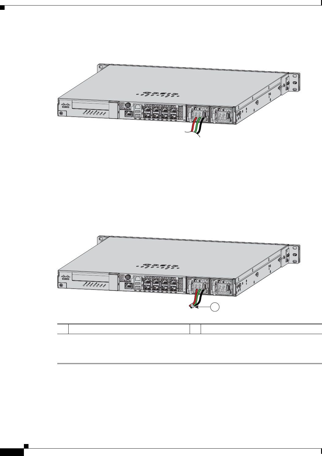
ground wire. Figure 6-21 shows the DC power supply with the wires inserted and the tie wrap secured.
Figure 6-21 Complete DC Secure Tie Wrap
Step 10
Remove the tape (if any) from the circuit breaker switch handle, and move the circuit breaker switch
handle to the On position. The power supply indicators light up when power is supplied to the appliance.
333060
1 Lead wires secured with a tie wrap
333061
1