


9-12
Cisco Intrusion Prevention System Appliance and Module Installation Guide for IPS 7.1
OL-24002-01
Chapter 9 Installing and Removing the ASA 5585-X IPS SSP
Verifying the Status of the ASA 5585-X IPS SSP
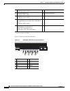
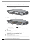
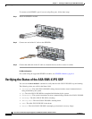
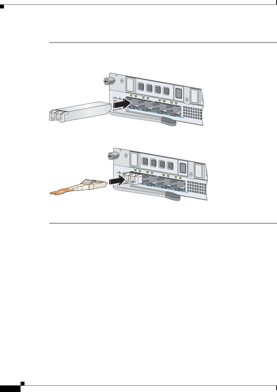
To connect to the SFP/SFP+ port if you are using fiber ports, follow these steps:
Step 1
Install the SFP/SFP+ module.
Step 2
Connect one end of the LC cable to the SFP/SFP+.
Step 3
Connect the other end of the LC cable to a network device, such as a router or switch.
For More Information
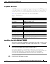
For a table listing the supported SFP/SFP+ modules, see SFP/SFP+ Modules, page 9-9.
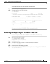
Verifying the Status of the ASA 5585-X IPS SSP
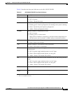
You can use the show module 1 command to verify that the ASA 5585-X IPS SSP is up and running.
The following values are valid for the Status field:
• Initializing
—The ASA 5585-X IPS SSP is being detected and the control communication is
being initialized by the system.
• Up
—The ASA 5585-X IPS SSP has completed initialization by the system.
• Unresponsive
—The system encountered an error communicating with the ASA 5585-X IPS SSP.
• Reloading
—The ASA 5585-X IPS SSP is reloading.
• Shutting Down
—The ASA 5585-X IPS SSP is shutting down.
• Down
—The ASA 5585-X IPS SSP is shut down.
• Recover
—The ASA 5585-X IPS SSP is attempting to download a recovery image.
9
8
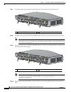
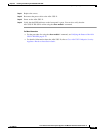
SFP/SFP+
7
6
253906
9
8
SFP/SFP+
7
6
253907