


5-43
Cisco Intrusion Prevention System Appliance and Module Installation Guide for IPS 7.1
OL-24002-01
Chapter 5 Installing the IPS 4270-20
Installing and Removing Interface Cards
Installing and Removing Interface Cards
Caution
Follow proper safety procedures when performing these steps by reading the safety warnings in
Regulatory Compliance and Safety Information for the Cisco Intrusion Prevention System 4200 Series
Appliance Sensor.
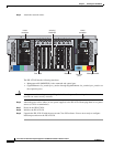
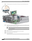
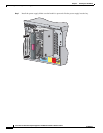
The IPS 4270-20 has nine expansion card slots. Slots 1 and 2 are PCI-X slots and are reserved for future
use. Slots 3 through 9 are PCI-Express slots. All slots are full-height slots. Slot 9 is populated by a RAID
controller card and is not available for use by network interface cards. The IPS 4270-20 supports two
10GE fiber interface cards, which you can install in any of the supported six slots (slots 3 to 8).
Caution
To prevent damage to the IPS 4270-20 or the expansion cards, power down the IPS 4270-20 and remove
all AC power cables before removing or installing expansion cards.
Caution
To prevent improper cooling and thermal damage, do not operate the IPS 4270-20 unless all expansion
slots have a cover or a card installed.
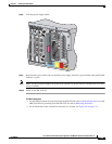
To install and remove interface cards, follow these steps:
Step 1
Log in to the CLI.
Step 2
Prepare the IPS 4270-20 to be powered off. Wait for the power down message before continuing with
Step 3.
sensor# reset powerdown
Note
You can also power off the IPS 4270-20 using the IDM or the IME.
Step 3
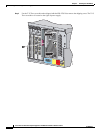
Power off the IPS 4270-20.
Step 4
Remove the power cables from the IPS 4270-20.
Step 5
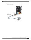
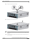
If rack-mounted, extend the IPS 4270-20 from the rack.
Step 6
Make sure the IPS 4270-20 is in an ESD-controlled environment.
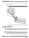
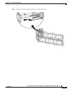
Step 7
Remove the chassis cover.