


8-8
Cisco Intrusion Prevention System Appliance and Module Installation Guide for IPS 7.1
OL-24002-01
Chapter 8 Installing and Removing the ASA 5500 AIP SSM
Installation and Removal Instructions
Step 5
Locate the grounding strap from the accessory kit and fasten it to your wrist so that it contacts your bare
skin. Attach the other end to the chassis.
Step 6
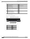
Remove the two screws at the left back end of the chassis.
Step 7
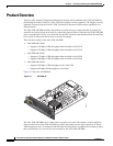
Remove the ASA 5500 AIP SSM and set it aside.
Note
If you are not replacing the ASA 5500 AIP SSM immediately, install the blank slot cover. Slot
covers must cover all empty slots. This prevents EMI from disrupting other equipment.
Step 8
If you need to replace the existing the ASA 5500 AIP SSM, insert the new ASA 5500 AIP SSM through
the slot opening.
Note
Do not replace the ASA 5500 AIP SSM with a different model. The the adaptive security
appliance will not recognize it.
Step 9
Attach the screws to secure the ASA 5500 AIP SSM to the chassis.
Step 10
Power on the adaptive security appliance.
Step 11
Reset the ASA 5500 AIP SSM.
asa# hw-module module 1 reset
Reset module in slot 1? [confirm]
Step 12
Press Enter to confirm.
Step 13
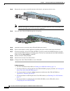
Check the indicators to see if the ASA 5500 AIP SSM is properly installed. If the ASA 5500 AIP SSM
is properly installed, the POWER indicator is solid green and the STATUS indicator is flashing green.
Or you can verify installation using the show module 1command.
For More Information
•
For more information on ESD, see Safety Recommendations, page 2-2.
•
For the procedure for verifying whether the ASA 5500 AIP SSM is properly installed, see Verifying
the Status of the ASA 5500 AIP SSM, page 8-7.