


4-7
Cisco Intrusion Prevention System Appliance and Module Installation Guide for IPS 7.1
OL-24002-01
Chapter 4 Installing the IPS 4260
Front and Back Panel Features
Front and Back Panel Features
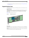
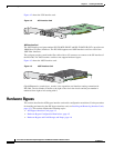
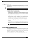
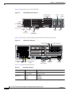
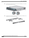
This section describes the IPS 4260 front and back panel features and indicators. Figure 4-4 shows the
front view of IPS 4260.
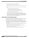
Figure 4-4 IPS 4260 Front Panel Features
•
There are three switches on the front panel of IPS 4260:
•
Power—Toggles the system power.
•
Reset—Resets the system.
•
ID—Toggles the system ID indicator.
Table 4-1 describes the front panel indicators on IPS 4260.
Cisco IPS 4260 series
Intrusion Prevention Sensor
POWER STATUSFLASH
ID NIC
Power
Flash
Status
ID
NIC
RESET
ID
153095
POWER
RESET
ID
Table 4-1 Front Panel Indicators
Indicator Description
ID (blue) Continuously lit when activated by the front panel ID switch.
NIC (green) Indicates activity on either the GigabitEthernetO/1 or MGMT interfaces.
Power (green) When continuously lit, indicates DC power. The indicator is off when power is
turned off or the power source is disrupted.
Flash (green/amber) Off when the compact flash device is not being accessed. Blinks green when the
compact flash device is being accessed. Solid amber when a device has failed.
Status (green/amber) Blinks green while the power-up diagnostics are running or the system is
booting. Solid green when the system has passed power-up diagnostics. Solid
amber when the power-up diagnostics have failed.