


5-51
Cisco Intrusion Prevention System Appliance and Module Installation Guide for IPS 7.1
OL-24002-01
Chapter 5 Installing the IPS 4270-20
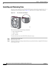
Installing and Removing Fans
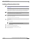
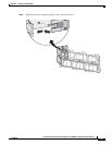
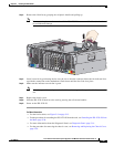
Step 4
Remove the failed fan by grasping the red plastic handle and pulling up.
Note
Remove and replace one fan at a time. If the IPS 4270-20 detects two failed fans, it shuts down
to avoid thermal damage.
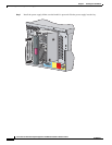
Step 5
Install a new fan by positioning the fan over the slot so that the connector below the fan indicator lines
up with the connection on the motherboard. Push down until the fan clicks in to place.
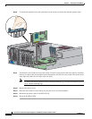
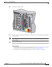
Step 6
Make sure the indicator on each fan is green.
Note
If the front panel internal system health indicator is not green after you install a fan, reseat the
fan.
Step 7
Replace the chassis cover.
Step 8
Slide the IPS 4270-20 back in to the rack by pressing the rail-release handles.
Step 9
Power on the IPS 4270-20.
For More Information
•
For the fan locations, see Figure 5-9 on page 5-13.
•
For the procedure for extending the IPS 4270-20 from the rack, see Extending the IPS 4270-20 from
the Rack, page 5-26.
•
For more information about the Diagnostic Panel, see Diagnostic Panel, page 5-14.
•
For the procedure for removing the chassis cover, see Removing and Replacing the Chassis Cover,
page 5-39.
250203
1
23
45
6
78
9
P
C
I-
E
x
4
P
C
I-
E
x
8P
C
I-
E
x
4P
C
I-
E
x
8
P
C
I
-
E
x
4
P
C
I-
X
1
0
0
M
H
z
U
I
D
P
S
2
Res
erved
for
Future Us
e
CONSOLE
MGMT 0/0
P
S
1