


D-24
Cisco Intrusion Prevention System Appliance and Module Installation Guide for IPS 7.1
OL-24002-01
Appendix D Upgrading, Downgrading, and Installing System Images
Installing System Images
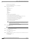
Step 3
Enter enable mode.
asa# enable
Step 4
Configure the recovery settings for the ASA 5585-X IPS SSP.
asa (enable)# hw-module module 1 recover configure
Note
If you make an error in the recovery configuration, use the hw-module module 1 recover stop
command to stop the system reimaging and then you can correct the configuration.
Step 5
Specify the TFTP URL for the software image.
Image URL [tftp://0.0.0.0/]:
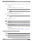
Example
Image URL [tftp://0.0.0.0/]: tftp://192.0.2.0/IPS-SSP_40-K9-sys-1.1-a-7.1-3-E4.img
Step 6
Specify the command and control interface of the ASA 5585-X IPS SSP.
Note
The port IP address is the management IP address of the ASA 5585-X IPS SSP.
Port IP Address [0.0.0.0]:
Example
Port IP Address [0.0.0.0]: 10.89.149.231
Step 7
Leave the VLAN ID at 0.
VLAN ID [0]:
Step 8
Specify the default gateway of the ASA 5585-X IPS SSP.
Gateway IP Address [0.0.0.0]:
Example
Gateway IP Address [0.0.0.0]: 10.89.149.254
Step 9
Execute the recovery. This transfers the software image from the TFTP server to the
ASA 5585-X IPS SSP and restarts it.
asa# hw-module module 1 recover boot
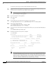
Step 10
Periodically check the recovery until it is complete.
Note
The status reads
Recovery
during recovery and reads
Up
when installation is complete.
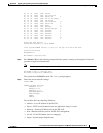
asa# show module 1 details
Getting details from the Service Module, please wait...
ASA 5585-X IPS Security Services Processor-10 with 8GE
Model: ASA5585-SSP-IPS40
Hardware version: 1.0
Serial Number: JAF1350ABSL
Firmware version: 2.0(1)3
Software version: 7.1(3)E4
MAC Address Range: 8843.e12f.5414 to 8843.e12f.541f