


5-39
Cisco Intrusion Prevention System Appliance and Module Installation Guide for IPS 7.1
OL-24002-01
Chapter 5 Installing the IPS 4270-20
Removing and Replacing the Chassis Cover
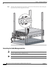
For More Information
•
For more information on working with electrical power and in an ESD environment, see Safety
Recommendations, page 2-2.
•
For more information on the best place to position your sensor on the network, see Your Network
Topology, page 1-3.
•
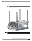
For the procedure for installing the IPS 4270-20 in a rack, see Installing the IPS 4270-20 in the
Rack, page 5-18.
•
For the instructions for setting up a terminal server, see Connecting an Appliance to a Terminal
Server, page 1-22.
•
For the procedure for using the setup command to initialize the IPS 4270-20, see Chapter B,
“Initializing the Sensor.”.
•
For the procedure for obtaining the most recent Cisco IPS software, see Obtaining Cisco IPS
Software, page C-1.
•
For the procedure for using HTTPS to log in to the IDM, refer to Logging In to the IDM.
•
For the procedures for configuring intrusion prevention on your sensor, refer to the following guides:
–
Cisco Intrusion Prevention System Device Manager Configuration Guide for IPS 7.1
–
Cisco Intrusion Prevention System Manager Express Configuration Guide for IPS 7.1
–
Cisco Intrusion Prevention System Sensor CLI Configuration Guide for IPS 7.1
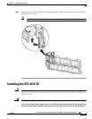
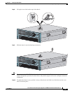
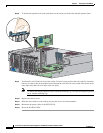
Removing and Replacing the Chassis Cover
Caution
Follow proper safety procedures when performing these steps by reading the safety warnings in
Regulatory Compliance and Safety Information for the Cisco Intrusion Prevention System 4200 Series
Appliance Sensor.
Warning
This product relies on the building’s installation for short-circuit (overcurrent) protection. Ensure that
the protective device is rated not greater than 120 VAC, 20 A U.S. (240 VAC, 16-20 A International).
Statement 1005
Warning
This equipment must be grounded. Never defeat the ground conductor or operate the equipment in the
absence of a suitably installed ground conductor. Contact the appropriate electrical inspection
authority or an electrician if you are uncertain that suitable grounding is available. Statement 1024
Warning
Blank faceplates and cover panels serve three important functions: they prevent exposure to
hazardous voltages and currents inside the chassis; they contain electromagnetic interference (EMI)
that might disrupt other equipment; and they direct the flow of cooling air through the chassis. Do not
operate the system unless all cards, faceplates, front covers, and rear covers are in place. Statement
1029