


5-42
Cisco Intrusion Prevention System Appliance and Module Installation Guide for IPS 7.1
OL-24002-01
Chapter 5 Installing the IPS 4270-20
Accessing the Diagnostic Panel
Note
Make sure the chassis cover is securely locked in to place before powering up the IPS 4270-20.
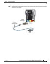
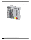
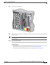
Step 11
Reattach the power cables to the IPS 4270-20.
Step 12
Reinstall the IPS 4270-20 in a rack, on a desktop, or on a table, or extend it back in to the rack.
Step 13
Power on the IPS 4270-20.
For More Information
•
For the procedure extending the IPS 4270-20 from the rack, see Extending the IPS 4270-20 from the
Rack, page 5-26.
•
For more information on working in an ESD-controlled environment, see Working in an ESD
Environment, page 2-4.
•
For the IDM procedure for powering down the IPS 4270-20, refer to Rebooting the Sensor; for the
IME procedure for powering down the IPS 4270-20, refer to Rebooting the Sensor.
•
For an illustration of the screwdriver and where it is located, see Figure 5-7 on page 5-10.
•
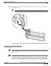
For the procedure for installing the power cables on the IPS 4270-20, see Installing the IPS 4270-20,
page 5-35.
•
If you are reinstalling the IPS 4270-20 in a rack, see Installing the Rail System Kit, page 5-16.
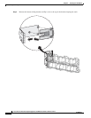
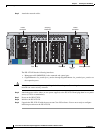
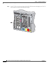
Accessing the Diagnostic Panel
Note
When you remove the chassis cover to view the Diagnostic Panel, leave the IPS 4270-20 powered on.
Powering off the IPS 4270-20 clears the Diagnostic Panel indicators.
To access the Diagnostic Panel, follow these steps:
Step 1
Extend the IPS 4270-20 from the rack.
Step 2
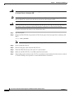
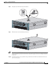
Remove the chassis cover.
Step 3
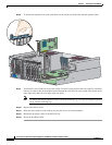
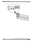
Locate the Diagnostic Panel. Follow the instructions in this chapter to remove and install failed
components. For aid in troubleshooting, use the internal health indicators information when contacting
TAC.
For More Information
•
For the procedure for extending the IPS 4270-20 from the rack, see Extending the IPS 4270-20 from
the Rack, page 5-26.
•
For the procedure for removing the chassis cover, see Removing and Replacing the Chassis Cover,
page 5-39.
•
For the location of the Diagnostic Panel, see Figure 5-9 on page 5-13.
•
For information on what internal health information each indicator displays on the Diagnostic Panel,
see Diagnostic Panel, page 5-14.