


4-18
Cisco Intrusion Prevention System Appliance and Module Installation Guide for IPS 7.1
OL-24002-01
Chapter 4 Installing the IPS 4260
Installing the IPS 4260
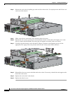
Step 6
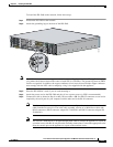
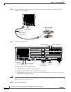
Connect the RJ-45 connector to the console port and connect the other end to the DB-9 or DB-25
connector on your computer.
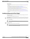
Step 7
Attach the network cables.
The IPS 4260 has the following interfaces:
•
GigabitEthernet0/1 (GE 0/1) is the sensing port.
•
Management0/0 (MGMT) is the command and control port.
•
GigabitEthernetslot_number/port_number through GigabitEthernetslot_number/port_number are
the additional expansion port slots.
Caution
Management and console ports are privileged administrative ports. Connecting them to an untrusted
network can create security concerns.
Step 8
Power on the IPS 4260.
153309
RJ-45 to
DB-9 or DB-25
serial cable
(null-modem)
Computer serial port
DB-9 or DB-25
MGMTCONSOLE
Console
port (RJ-45)
153308
6
5
4
SPD indicator
Link/ACT indicator
GE 0/1CONSOLE
MGMT
SPD
LNK
SPD
LNK
SPD indicator
"SPD"
Link/ACT indicator
"LINK"
Diagnostic
indicators
(for TAC use)
System ID
indicator
Status
indicator