


3-9
Cisco Intrusion Prevention System Appliance and Module Installation Guide for IPS 7.1
OL-24002-01
Chapter 3 Installing the IPS 4240 and IPS 4255
Installing the IPS 4240 and IPS 4255
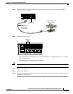
Step 6
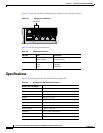
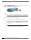
Connect the RJ-45 connector to the console port and connect the other end to the DB-9 or DB-25
connector on your computer.
Step 7
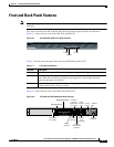
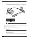
Attach the network cables.
•
GigabitEthernet0/0, GigabitEthernet0/1, GigabitEthernet0/2, and GigabitEthernet0/3 (from right to
left) are sensing ports.
•
Management0/0 is the command and control port.
Caution
Management and console ports are privileged administrative ports. Connecting them to an untrusted
network can create security concerns.
Step 8
Power on the appliance.
Step 9
Initialize the appliance.
Step 10
Upgrade the appliance with the most recent Cisco IPS software. You are now ready to configure intrusion
prevention on the appliance.
114418
RJ-45 to
DB-9 or DB-25
serial cable
(null-modem)
Computer serial port
DB-9 or DB-25
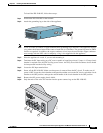
FLASH
CONSOLE
AUX
POWER
STATUS
FLASH
Console
port (RJ-45)
114417
USB2
USB1
LNK SPD
3
LNK SPD
2
LNK SPD
1
LNK SPD
0
MGMT
Indicators