


5-11
Cisco Intrusion Prevention System Appliance and Module Installation Guide for IPS 7.1
OL-24002-01
Chapter 5 Installing the IPS 4270-20
Front and Back Panel Features
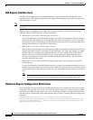
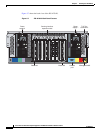
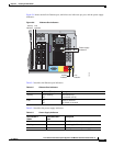
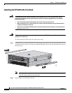
Figure 5-8 shows the built-in Ethernet port, which has two indicators per port, and the power supply
indicators.
Figure 5-8 Ethernet Port Indicators
Table 5-2 describes the Ethernet port indicators.
Table 5-3 describes the power supply indicators.
1
234
PCI-E x4 PCI-X 100 MHz
PS1
Reserved
for
Future Use
CONSOLE
MGMT 0/0
250085
Activity
indicator
Link
indicator
Power supply
indicators
Activity
indicator
Link
indicator
Table 5-2 Ethernet Port Indicators
Indicator Indicator (Green) Description
Activity On or flashing
Off
Network activity
No network activity
Link On
Off
Linked to network
Not linked to network
Table 5-3 Power Supply Indicators
Fail Indicator 1
Amber
Power Indicator 2
Green
Description
Off Off No AC power to any power supply
Flashing Off Power supply failure (over current)
On Off No AC power to this power supply