


4-23
Cisco Intrusion Prevention System Appliance and Module Installation Guide for IPS 7.1
OL-24002-01
Chapter 4 Installing the IPS 4260
Installing and Removing the Power Supply
For More Information
•
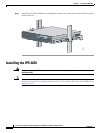
For the procedure for attaching power cords and cables to the IPS 4260, see Installing the IPS 4260,
page 4-16.
•
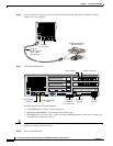
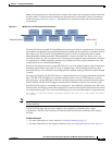
For an illustration of the expansion card slots, see Figure 4-6 on page 4-8.
•
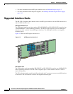
For an illustration of the supported PCI cards, see Supported Interface Cards, page 4-3.
•
For the IDM procedure for resetting the IPS 4260, refer to Rebooting the Sensor; for the IME
procedure for resetting the IPS 4260, refer to Rebooting the Sensor.
•
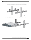
For the procedure for removing the IPS 4260 from a rack, see Rack Mounting, page 4-10.
•
For more information on ESD-controlled environments, see Safety Recommendations, page 2-2.
•
For the procedure for removing the chassis cover, see Removing and Replacing the Chassis Cover,
page 4-19.
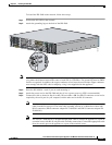
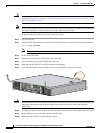
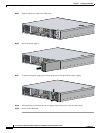
Installing and Removing the Power Supply
The IPS 4260 ships with one power supply, but you can order it with two power supplies so that you have
a redundant power supply.
To install and remove power supplies, follow these steps:
Step 1
Log in to the CLI.
Step 2
Prepare the IPS 4260 to be powered off. Wait for the power down message before continuing with Step 3.
sensor# reset powerdown
Note
You can also power off the IPS 4260 using the IDM or the IME.
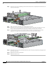
Step 3
Power off the IPS 4260.
Step 4
Remove the power cable and other cables from the IPS 4260.
Note
Power supplies are hot-swappable. You can replace a power supply while the IPS 4260 is
running, if you are replacing a redundant power supply.