


5-5
Cisco Intrusion Prevention System Appliance and Module Installation Guide for IPS 7.1
OL-24002-01
Chapter 5 Installing the IPS 4270-20
Hardware Bypass
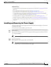
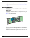
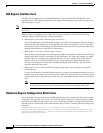
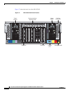
Figure 5-3 shows the 2SX interface card.
Figure 5-3 2SX Interface Card
10GE Interface Card
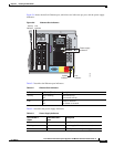
The 10GE interface card (part numbers IPS-2X10GE-SR-INT and IPS-2X10GE-SR-INT=) provides two
10000 Base-SX (fiber) interfaces. The IPS 4270-20 supports up to two 10GE interface cards for a total
of four 10GE fiber interfaces.
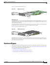
The card ports require a multi-mode fiber cable with an LC connector to connect to the SX interface of
the IPS 4270-20. The 10GE interface card does not support hardware bypass.
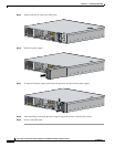
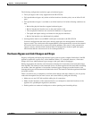
Figure 5-4 shows the 10GE interface card.
Figure 5-4 10GE Interface Card
GigabitEthernet slot_number/port_number is the expansion card interface naming convention for the
IPS 4270-20. The slot number is shown above the slot in the chassis and the port number is numbered
from top to bottom starting with 0.
Hardware Bypass
This section describes the 4GE bypass interface card and its configuration restrictions. For the procedure
for installing and removing the 4GE bypass interface card, see Installing and Removing Interface Cards,
page 5-43. This section contains the following topics:
•
4GE Bypass Interface Card, page 5-6
•
Hardware Bypass Configuration Restrictions, page 5-6
•
Hardware Bypass and Link Changes and Drops, page 5-7
190474
253975