


9-14
Cisco Intrusion Prevention System Appliance and Module Installation Guide for IPS 7.1
OL-24002-01
Chapter 9 Installing and Removing the ASA 5585-X IPS SSP
Removing and Replacing the ASA 5585-X IPS SSP
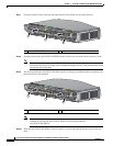
Step 7
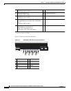
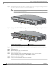
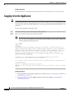
Grasp the ejection levers at the left and right bottom of the module slot and pull them out.
Step 8
Grasp the sides of the ASA 5585-X IPS SSP and pull it all the way out of the chassis and set it aside.
Note
If you are not replacing the ASA 5585-X IPS SSP immediately, install the blank slot tray. You
must install slot trays in all empty slots to maintain the proper air flow. This prevents EMI, which
can disrupt other equipment.
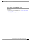
Step 9
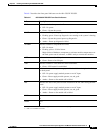
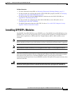
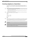
If you are replacing the ASA 5585-X IPS SSP, install it by lining it up with the module slot making sure
the ejection levers are extended.
Note
The ASA 5585-X IPS SSP must be at the same level as the ASA 5585-X SSP model; for
example, if you have the ASA 5585-X SSP-10, you can only install the
ASA 5585-X IPS SSP-10.
Step 10
Slide the ASA 5585-X IPS SSP in to the slot until it is seated, and push the ejection levers back in to
place.
1 ASA 5585-X IPS SSP 2 Ejection levers
PWR
BOOT
ALARM
ACT
VPN
PS1
HDD1
PS0
HDD0
USB
RESET
0
SFP1
SFP0
1
01234567
MGMT
0
1
AUX CON SOLE
253902
PWR
BOOT
ALARM
ACT
VPN
PS1
HDD1
PS0
HDD0
USB
RESET
0
SFP1
SFP0
101234567
MGMT
0
1
AUX CON SOLE
2
2
1
1 ASA 5585-X IPS SSP 2 Ejection levers
PWR
BOOT
ALARM
ACT
VPN
PS1
HDD1
PS0
HDD0
USB
RESET
0
SFP1
SFP0
1
01234567
MGMT
0
1
AUX CONSOLE
253903
PWR
BOOT
ALARM
ACT
VPN
PS1
HDD1
PS0
HDD0
USB
RESET
0
SFP1
SFP0
101234567
MGMT
0
1
AUX CONSOLE
2
2
1