


9-7
Cisco Intrusion Prevention System Appliance and Module Installation Guide for IPS 7.1
OL-24002-01
Chapter 9 Installing and Removing the ASA 5585-X IPS SSP
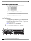
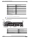
Front Panel Features
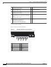
Table 9-2 describes the front panel indicators on the ASA 5585-X IPS SSP.
Table 9-2 ASA 5585-X IPS SSP Front Panel Indicators
Indicator Description
PWR Indicates whether the system is off or on:
•
Off—No power.
•
Green—System has power.
BOOT Indicates how the power-up diagnostics are proceeding:
•
Flashing green—Power-up diagnostics are running or the system is booting.
•
Green—System has passed power-up diagnostics.
•
Amber—Power-up diagnostics failed.
ALARM
1
1. The Cisco ASA software does not support the ALARM indicator initially; support will be added at a later date.
Indicates whether a component has failed:
•
Off—No alarm.
•
Flashing yellow—Critical alarm.
Major failure of hardware component or software module, temperature over
the limit, power out of tolerance, or OIR is ready to remove the module.
2
.
2. OIR is not available at this time.
ACT Indicates the status of an HA pair:
•
Green—Status of an HA pair.
VPN Indicates whether a VPN tunnel has been established:
•
Green—VPN tunnel is established.
PS1 Indicates the state of the power supply module installed on the right when facing
the back panel:
•
Off—No power supply module present or no AC input.
•
Green—Power supply module present, on, and good.
•
Amber—Power or fan module off or failed.
PS0 Indicates the state of the power module installed on the left when facing the back
panel:
•
Off—No power supply module present or no AC input.
•
Green—Power supply module present, on, and good.
•
Amber—Power or fan module off or failed.
HDD1 N/A
•
HDD2 N/A
•