


B-14
Cisco Intrusion Prevention System Appliance and Module Installation Guide for IPS 7.1
OL-24002-01
Appendix B Initializing the Sensor
Advanced Setup
Note
You do not need to configure interfaces on the ASA 5500 AIP SSM. You should ignore the
modify interface default VLAN setting. The separation of traffic across virtual sensors is
configured differently for the ASA 5500 AIP SSM than for other sensors.
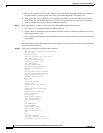
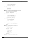
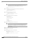
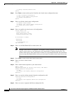
[1] Modify interface default-vlan.
Option:
Step 8
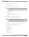
Press Enter to return to the top-level interface and virtual sensor configuration menu.
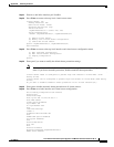
[1] Edit Interface Configuration
[2] Edit Virtual Sensor Configuration
[3] Display configuration
Option:
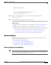
Step 9
Enter
2
to edit the virtual sensor configuration.
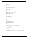
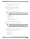
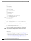
[1] Remove virtual sensor.
[2] Modify "vs0" virtual sensor configuration.
[3] Create new virtual sensor.
Option:
Step 10
Enter
2
to modify the virtual sensor vs0 configuration.
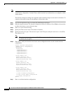
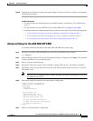
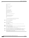
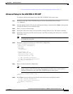
Virtual Sensor: vs0
Anomaly Detection: ad0
Event Action Rules: rules0
Signature Definitions: sig0
No Interfaces to remove.
Unassigned:
Monitored:
[1] GigabitEthernet0/1
Add Interface:
Step 11
Enter
1
to add GigabitEthernet 0/1 to virtual sensor vs0.
Note
Multiple virtual sensors are supported. The adaptive security appliance can direct packets to
specific virtual sensors or can send packets to be monitored by a default virtual sensor. The
default virtual sensor is the virtual sensor to which you assign GigabitEthernet 0/1. We
recommend that you assign GigabitEthernet 0/1 to vs0, but you can assign it to another virtual
sensor if you want to.
Step 12
Press Enter to return to the main virtual sensor menu.
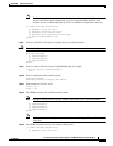
Step 13
Enter
3
to create a virtual sensor.
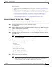
Name[]:
Step 14
Enter a name and description for your virtual sensor.
Name[]: newVs
Description[Created via setup by user cisco]: New Sensor
Anomaly Detection Configuration
[1] ad0
[2] Create a new anomaly detection configuration
Option[2]: