


6-22
Cisco Intrusion Prevention System Appliance and Module Installation Guide for IPS 7.1
OL-24002-01
Chapter 6 Installing the IPS 4345 and IPS 4360
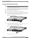
Removing and Installing the Power Supply
To connect the DC power supply on the appliance, follow these steps:
Step 1
Make sure that the chassis ground is connected on the chassis before you begin installing the DC power
supply.
Step 2
Turn off the circuit breaker to the power supply.
Step 3
From the front of the appliance, verify that the power switch is in the Standby position.
Step 4
Move the circuit-breaker switch handle to the Off position, and apply tape to hold it in the Off position.
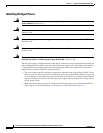
Step 5
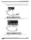
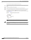
Use a 10 gauge wire-stripping tool to strip each of the three wires coming from the DC input power
source. Strip the wires to 0.27 inch (7 mm) +
0.02 inch (0.5 mm). Do not strip more than the
recommended length of wire because doing so could leave the wire exposed from the DC power supply
connection (Figure 6-18).
Figure 6-18 Stripping the DC Input Power Source Wire
Warning
An exposed wire lead from a DC input power source can conduct harmful levels of electricity. Be sure
that no exposed portion of the DC input power source wire extends from the terminal block plug.
Statement 122
1 We recommend that you strip the wire to 0.27 inch (7 mm).
333062
1