


5-49
Cisco Intrusion Prevention System Appliance and Module Installation Guide for IPS 7.1
OL-24002-01
Chapter 5 Installing the IPS 4270-20
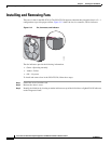
Installing and Removing the Power Supply
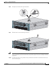
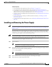
Step 8
Lock the power supply handle.
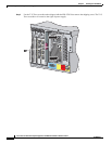
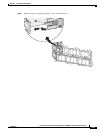
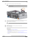
Step 9
Reconnect the power cables. Be sure that the power supply indicator is green and the front panel health
indicator is green.
Note
Make sure the two power supplies are powered by separate AC power sources so that the IPS 4270-20 is
always available.
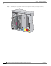
Step 10
Power on the IPS 4270-20.
For More Information
•
For the IDM procedure for powering down the IPS 4270-20, refer to Rebooting the Sensor; for the
IME procedure for powering down the IPS 4270-20, refer to Rebooting the Sensor.
•
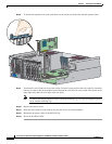
For an illustration of the screwdriver and where it is located, see Figure 5-9 on page 5-13.
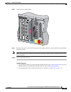
1
234
PCI-E x4 PCI-X 100 MHz
Reserved
for
Future Use
CONSOLE
M
GMT 0/0
PS1
250164